Panasonic GPH5D User Manual
Page 26
27
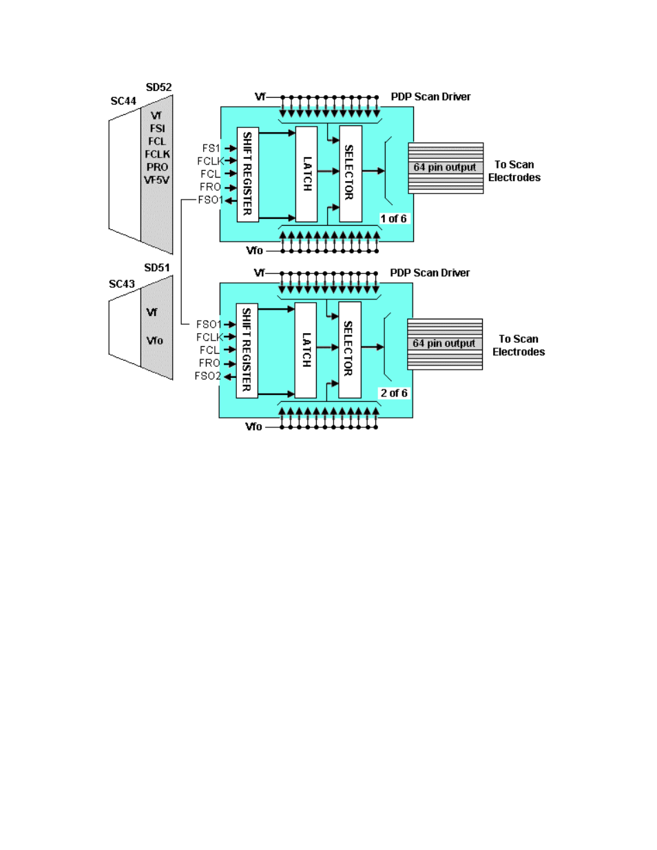
Figure 25
After the scan waveform is developed on the SC Board, it is applied to the SU
and SD boards for de-multiplexing. The signal is input to a series of shift registers
inside the PDP scan driver IC. Figure 25 shows an example of the de-
multiplexing circuit. There are six driver ICs on the SU board and six on the SD
board.
See also other documents in the category Panasonic Televisions:
- TX-43P400H (40 pages)
- TC-29V50R (28 pages)
- TX-43P800H (36 pages)
- TH-R50PY700 (22 pages)
- TX-51P250H (44 pages)
- TH-R50PV700 (22 pages)
- TX-47WG25 (60 pages)
- CT-3653 (80 pages)
- LIFI PT-61LCX70 (64 pages)
- CT 32D10 (36 pages)
- CT-G3349L (32 pages)
- TX-86W100A (48 pages)
- CT-L2000 (32 pages)
- VIERA TX-L37V10B (47 pages)
- PT-56LCZ70-K (68 pages)
- CT-36HX41U (58 pages)
- TC-26LX14 (58 pages)
- VIVA TH-65PZ750U (73 pages)
- CT-30WC15 (64 pages)
- CT-36SF24 (36 pages)
- Viera TY-WK42PR4W (52 pages)
- CT-3271S (32 pages)
- CTF2911 (58 pages)
- BT-LH1710E (5 pages)
- CT-30WC14 (96 pages)
- CT 20SL15 (68 pages)
- CT 27HL14 (80 pages)
- PT-50LCX63 (2 pages)
- CT-20G12 (24 pages)
- TC-42U12 (58 pages)
- PT-56LCX70 (64 pages)
- TC-17LA2D (32 pages)
- PT-43LC14 (88 pages)
- CT-36D20U (44 pages)
- CT-F2923X (73 pages)
- CT-20R14 (20 pages)
- Viera TC-P50ST50 (28 pages)
- TC-50PX14 (58 pages)
- CT 32HX40 (54 pages)
- TC-60PS34 (64 pages)
- CT-27G32 (32 pages)
- TX21FJ50A (22 pages)
- TC-26T1Z (60 pages)
- CT-32SX31CE (31 pages)
- TC-26LX70L (64 pages)