Cables you may need, Recommended order of installation – Paradyne Single T1 Network Access Module (NAM) 9161-A2-GN10-40 User Manual
Page 3
3
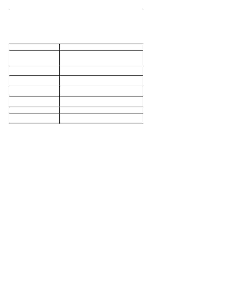
Cables You May Need
The following cables and connectors are specifically for this product. See
Warranty,
Sales, and Service Information on page 15 for ordering information. See the Technical
Reference for all cable pin-out information.
If connecting to a . . .
You need a . . .
Terminal/printer (DB25
interface/connector – EIA-232
connection)
COM Port-to-Terminal/Printer cable (14 ft.)
PC (DB9 interface/connector –
EIA-232 connection)
COM Port-to-PC cable (14 ft.)
DTE with a V.35
interface/connector
MS34 to DB25 adapter cable for each port: Port 1
and/or Port 2 (1 ft.)
DTE with a RS-449
interface/connector
DB37 to DB25 DTE adapter cable for each port:
Port 1 and/or Port 2 (1 ft.)
DTE with a V.11/X.21
interface/connector
DB15 to DB25 adapter cable for each port: Port 1
and/or Port 2 (1 ft.)
LAN Adapter
COM Port-to-LAN Adapter cable (14 ft.)
Modem (8-pin
modular-to-DB25 connector)
Modem cable
Recommended Order of Installation
1. First, install the I/O card.
2. Connect all cables into the I/O card.
3. Install the NAM.
4. Go to the appropriate housing installation document for power-up verification
procedures:
—
2-Slot Housing Installation Instructions (Document No. 9000-A2-GN15)
—
5-Slot Housing with AC Power Supply Installation Instructions (Document
No. 9000-A2-GN16)
—
5-Slot Housing with DC Power Supply Installation Instructions (Document
No. 9000-A2-GN1C)
—
9000 Series Access Carrier Installation Instructions (Document No.
9000-A2-GN1D)