0 configuration (model 2168 only), 1 configuring the hardware dip switches, Configuration (model 2168 only) – Patton electronic 2158 User Manual
Page 14: Configuring the hardware dip switches
14
4.0 CONFIGURATION (MODEL 2168 ONLY)
The CopperLink Ethernet Extender has eight DIP switches for configur-
ing the unit for a wide variety of applications. This section describes
switch locations and explains the different configurations.
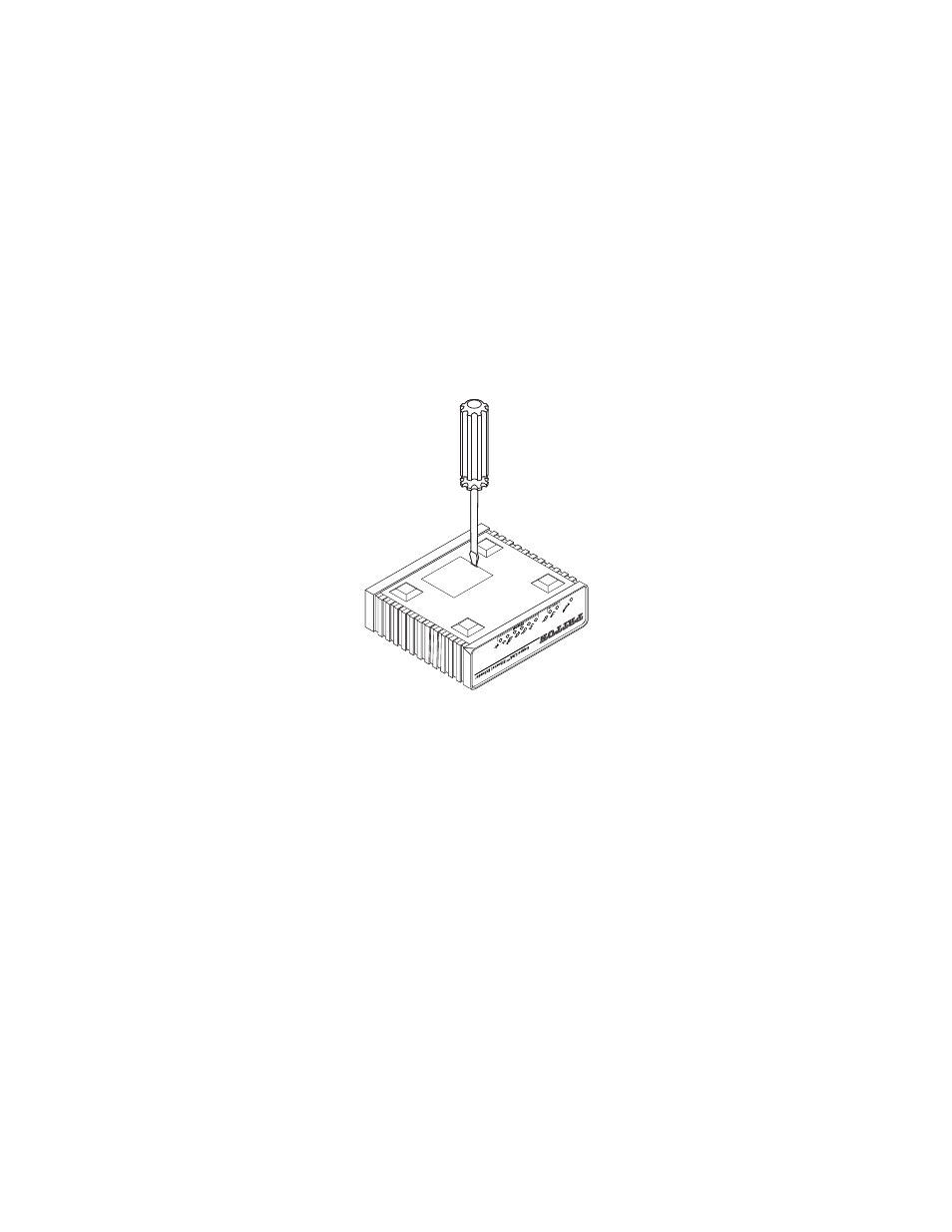
4.1 CONFIGURING THE HARDWARE DIP SWITCHES
Using a small flat-tip screwdriver, remove the protective cover located on
the underside of the CopperLink Ethernet Extender (see Figure 9).
Figure 9.
Removing protective cover
Figure 10 and Figure 11 on page 15 show the orientation of the DIP
switches in the On and Off positions.
See also other documents in the category Patton electronic Hardware:
- PATTON 2707/I (24 pages)
- 1015 (7 pages)
- ONSITE SERIES 2603 (133 pages)
- 2500RC (23 pages)
- 1094A (17 pages)
- 2135 (9 pages)
- 2720 (23 pages)
- 3210 (2 pages)
- IpLink 2888 (2 pages)
- 1025S (9 pages)
- 1004ABRC (13 pages)
- SMARTNODE 5400 (8 pages)
- 2312M (16 pages)
- Model 3088/I (61 pages)
- 3087 (10 pages)
- Patton RAS 3120 (2 pages)
- 1140 (8 pages)
- 2707D (20 pages)
- T1/E1 CHANNELIZED GIGABIT ROUTER 2884 (51 pages)
- CopperLink Ethernet Extenders 2158A (28 pages)
- 1170M SERIES (16 pages)
- CopperLink 07M2160-GS (107 pages)
- 1082/I (28 pages)
- 2884 (52 pages)
- 1002S (8 pages)
- 1058DVs (5 pages)
- S-DTA (30 pages)
- GoCard 1058 (2 pages)
- 1050patton (9 pages)
- 460 (5 pages)
- SMARTNODE 1400 (16 pages)
- G.SHDSL INTEGRATED 3086 (196 pages)
- 2620 (12 pages)
- 2020P (9 pages)
- 2192 (28 pages)
- 1053AS (2 pages)
- 1017 (5 pages)
- 1193 (11 pages)
- 504 (8 pages)
- SMARTNODE 4960 (68 pages)
- Industrial Ethernet Extender with LCD Interface 3231 (2 pages)
- Patton SmartNode 2300 Series (2 pages)
- 1092ARC (20 pages)
- Model 2711 (13 pages)
- 2701/D (28 pages)