Setting up your system, Antenna 75 ω antenna 75 ω, Digital audio out – Philips ShowView MX5100VR/02 User Manual
Page 7: Av2 (decoder) av1(tv), Vcr dvd/vcr tv antenna av2 (decoder) av1(tv)
7
English
Setting Up your System
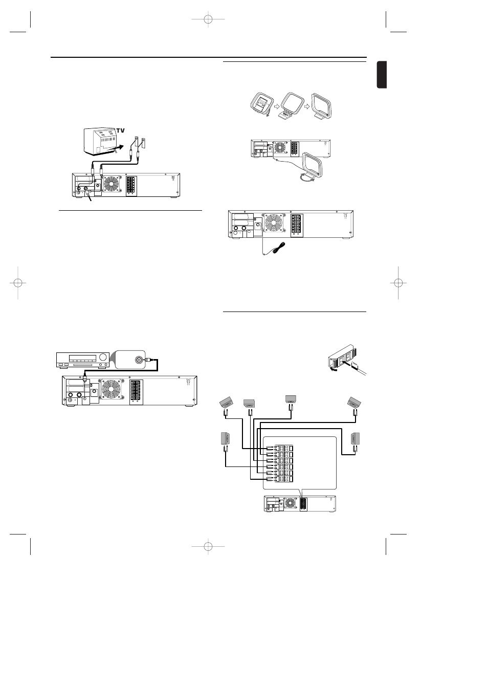
Connecting to Optional Equipment
(for DVD features)
• A digital component with a built-in MPEG 2 or Dolby
Digital
TM
decoder allows you to enjoy the surround sound
while producing the effect of being in a movie theater or a
concert hall.
• The player outputs the surround sound signals from the DIG-
ITAL OUT COAXIAL connector.
If your receiver has a MPEG 2 or Dolby Digital™ decoder,
1 Connect the COAXIAL DIGITAL AUDIO OUT of the System
to the COAXIAL DIGITAL AUDIO IN on your receiver.
Notes:
– If the audio format of the digital output does not match
the capabilities of your receiver, the receiver will pro-
duce a strong, distorted sound or no sound at all.
– MP3 Audio is not available on the Digital Output.
– You will still need the video cable or RF coaxial cable for
VCR features.
If your TV is not equipped with a SCART input, you can select
the following connection:
If your TV has a S-Video input connector,
1 Connect the antenna or cable to the AERIAL of your System.
2 Connect the S-Video out on the System to the S-Video in on
the TV.
3 Connect the COAXIAL (Digital audio out) on the System to
the Coaxial jack on the TV.
Note:
– You will still need the SCART cable for VCR features.
ANTENNA 75
Ω
ANTENNA 75
Ω
FM
(75
Ω)
DIGITAL
AUDIO OUT
COAXIAL
S-VIDEO
OUT
MW
FL
FR
C
SL
SR
W
SPEAKER (4
Ω)
RF OUT
AERIAL
VCR
DVD/VCR
TV ANTENNA
AV2
(DECODER)
AV1(TV)
COAXIAL DIGITAL
AUDIO IN
AUDIO RECEIVER
Antenna Connections
MW Antenna
1 Fix the antenna holder as shown.
2 Connect the supplied MW antenna to the MW jack, then posi-
tion it to receive the clearest sound.
ANTENNA 75
Ω
ANTENNA 75
Ω
FM
(75
Ω)
DIGITAL
AUDIO OUT
COAXIAL
S-VIDEO
OUT
MW
FL
FR
C
SL
SR
W
SPEAKER (4
Ω)
RF OUT
AERIAL
VCR
DVD/VCR
TV ANTENNA
AV2
(DECODER)
AV1(TV)
FM Antenna
1 Connect the supplied FM antenna to the FM jack. Extend the
FM antenna wire and fix its end to the wall.
ANTENNA 75
Ω
ANTENNA 75
Ω
FM
(75
Ω)
DIGITAL
AUDIO OUT
COAXIAL
S-VIDEO
OUT
MW
FL
FR
C
SL
SR
W
SPEAKER (4
Ω)
RF OUT
AERIAL
VCR
DVD/VCR
TV ANTENNA
AV2
(DECODER)
AV1(TV)
Notes:
– Do not place the MW antenna on the System. Keep it as
possible from the System and the speaker wires. Keep it
away from the AC power cords of the System and other
equipment.
– For better FM reception, connect an outdoor FM anten-
na (not supplied) to the ANTENNA 75 ohm jack.
Connecting the speaker wires to the speak-
er jacks
ANTENNA 75
Ω
ANTENNA 75
Ω
FM
(75
Ω)
DIGITAL
AUDIO OUT
COAXIAL
S-VIDEO
OUT
MW
FL
FR
C
SL
SR
W
SPEAKER (4
Ω)
RF OUT
AERIAL
VCR
DVD/VCR
TV ANTENNA
AV2
(DECODER)
AV1(TV)
Center Speaker
Subwoofer
Front
Speaker
(right)
Rear Speaker
(right surround)
Rear Speaker
(left surround)
Front
Speaker
(left)
FL (Front Left - white)
FR (Front Right - red)
C (Center - green)
SL (Surround/Rear Left - blue)
SR (Surround/Rear Right - grey)
W (Subwoofer - purple)
1
Connect the supplied speakers using the sup-
plied speaker wires. Match the colors of the
wires to the colors on the jacks. Hold down
the jack tab while inserting the stripped por-
tion of the speaker wire into the jack.Then,
release the tab. Make sure you do not insert
the wire too far. None of the rubber-coated
wire should be clamped by the jack tab.
ANTENNA 75
Ω
ANTENNA 75
Ω
FM
(75
Ω)
DIGITAL
AUDIO OUT
COAXIAL
S-VIDEO
OUT
MW
FL
FR
C
SL
SR
W
SPEAKER (4
Ω)
RF OUT
AERIAL
VCR
DVD/VCR
TV ANTENNA
AV2
(DECODER)
AV1(TV)
E9017FD_EN.qx3 03.8.6 10:13 AM Page 7