Preparation, A am loop antenna connection, B fm wire antenna connection – Philips - FW768P User Manual
Page 11: C speakers connection, G subwoofer out connection, H line out connection, I connecting other equipment to your system, J ac power supply, Inserting batteries into the remote control, D rear speakers’ connection
11
English
A AM Loop Antenna
Connection
Connect the supplied loop antenna to the
AM ANTENNA terminal. Place the AM loop
antenna far away from the system and
adjust its position for the best reception.
B FM Wire Antenna
Connection
Connect the supplied FM wire antenna to
the FM ANTENNA 300
Ω
terminal. Adjust
the position of the FM antenna for the best
reception.
Outdoor Antenna
For better FM stereo reception, connect an
outdoor FM antenna to the FM ANTENNA
300
Ω
terminal using a 300
Ω
dipole wire.
C Speakers Connection
• Connect the right speaker to Front
terminal R, with the red wire to + and
the black wire to -.
• Connect the left speaker to Front
terminal L, with the red wire to + and
the black wire to -.
• Clip the stripped portion of the speaker
wire as shown.
unlock
lock
12 mm
G Subwoofer Out Connection
Connect the supplied active subwoofer
SW030 to the SUBWOOFER OUT terminal.
The subwoofer reproduces just the low
bass effect (e.g. explosions, the rumble of
spaceships, etc.). Be sure to follow the
instructions supplied with the subwoofer.
H Line Out Connection
(wireless
ready)
You can connect the audio left and right
LINE OUT terminals to a optional CD
Recorder ANALOGUE IN terminals. This
allows you to record in an analogue format.
You can also install additional optional
front active speakers away from the
system (e.g. in another room) to reduce the
inconvenience of running long speaker
wires across rooms. You can place as many
remote speakers as you like provided they
operate at the same radio frequency.
Connect the wireless radio frequency
transmitter to the LINE OUT terminals.
Place the active speakers at your preferred
location. Be sure to follow the instructions
supplied with the active speakers.
PREPARATION
I Connecting other
equipment to your system
You can connect the audio left and right
OUT terminals of a TV, VCR, Laser Disc
player, DVD player or CD-Recorder to the
AUX/CDR IN terminals at the rear of the
system.
J AC Power Supply
After all other connections have been
made, connect the AC power cord to the
system and to the wall outlet.
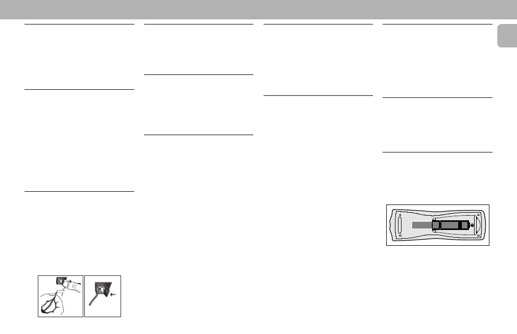
Inserting batteries into the
Remote Control
• Insert the batteries (Type R06 or AA)
into the remote control as shown in the
battery compartment.
+
-
+
-
• To avoid damage from possible battery
leakage, remove dead batteries or
batteries that will not be used for a long
time. For replacement, use type R06 or
AA batteries.
D Rear Speakers’ Connection
Connect the black (non-marked) wires to
the black REAR SURROUND terminals and
the white (marked wires) to the grey REAR
SURROUND terminals.
E Center Speaker
Connection
Connect the black (non-marked) wires to
the black CENTER terminal and the blue
(marked wires) to the blue CENTER
terminal.
F Wireless Surround Out
Connection
You may connect transmitter unit of the
wireless rear speakers
(not supplied) to the
SURROUND OUT terminal instead of the
wired rear speakers. Be sure to follow the
instructions supplied with the wireless rear
speakers.
Note:
– Availability of wireless transmitter and
its peripherals are subjected to the
approval of local authorities. Please
check with respective local safety or
approving authority.