Patton electronic 1094A User Manual
Page 9
5
5..0
0 O
OP
PE
ER
RA
AT
TIIO
ON
N
Once the Model 1094A is properly configured and installed, it
should operate transparently. This sections describes power-up, read-
ing the LED status monitors, and using the built-in loopback test
modes.
5.1 POWER-UP
To apply power to the Model 1094A, first be sure that you have
read Section 4.3, and that the unit is connected to the appropriate
power source. Then power-up the unit using the rear power switch.
5.2 LED STATUS MONITORS
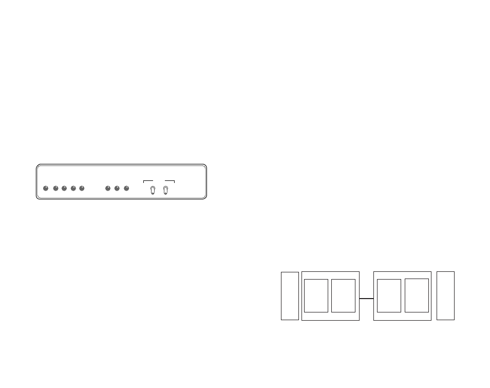
The Model 1094A features eight front panel LEDs that monitor
power, the DTE signals, network connection and test modes. Figure 5
(below) shows the front panel location of each LED. Following Figure
5 is a description of each LEDs function.
TD & RD
Glows yellow to indicate an idle condition of Binary
“1” data on the respective terminal interface sig-
nals. Green indicates Binary “0” data
CTS
Glows green to indicate that the Clear to Send sig-
nal from the modem is active.
CD
Glows yellow if no carrier signal is being received
from the remote modem. Green indicates that the
remote modem’s carrier is being received.
DTR
Glows green to indicate that the Data Terminal
Ready signal from the terminal is active.
15
Model 1092
KiloModem 2W High Speed 2-Wire Short Range Modem
RD
TD
CTS
CD
DTR
ER
NS
TM
Test Modes
Control Port
Local -
Normal -
Remote -
- 511E
- Normal
- 511
Figure 5. Model 1094A Front Panel
ER
- blinks ON/OFF after a 511/511E test has timed
out. See Section 5.3.3 (Test Pattern Generator) for
more information.
- flashes once to indicate that a CRC error has
occurred (during normal operation) or bit errors
have occurred (during 511/511E tests).
- Only at power up, blinks once every 200 ms if
the DTE Rate is set to an unsupported settings
TM
glows yellow to indicate that the Model 1094A
has been placed in Test Mode. The unit can be
placed in test mode by the local user or by the
remote user.
NS
(No Signal) glows red to indicate that the local
Model 1094A is not connected with the remote
Model 1094A.
5.3 TEST MODES
The Model 1094A offers two proprietary loopback test modes, plus
a built-in V.52 BER test pattern generator to evaluate the condition of
the modems and the communication link. These tests can be activat-
ed physically from the front panel or via the DTE interface.
5.3.1 Overview
Figure 6 below shows the major elements used in the loop-back
and pattern tests available in the Model 1094A. Each block has sever-
al functions. Following Figure 6 are descriptions that show how the
elements are used during Test Modes.
Figure 6: Block Diagram Model 1094A
16
Pattern
Gen/Det
Loop
Contr
ol
Loop
Contro
l
Pattern
Gen/Det
Processor
Processor
Framer
Framer
Line