Patton electronic 1094A User Manual
Page 5
7
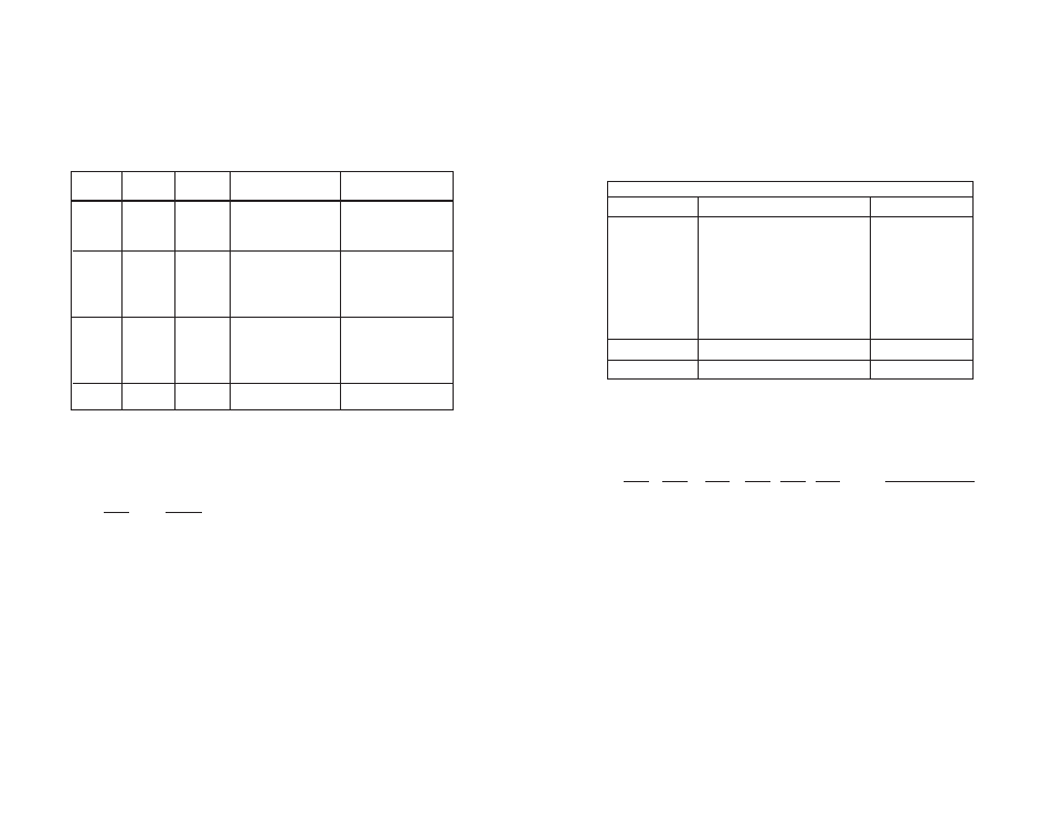
Switches S2-6 and S2-7: Clock Mode
Use Switches S2-6 and S2-7 to configure the 1094A for internal,
external, or receive recover clock mode.
Switch S2-8: Enable/Disable Loop Tests from DTE
Use Switch S2-8 to allow Model 1094A to enter loopback tests
when the DTE raises the appropriate loop request pin.
S2-8
Setting
On
Response to DTE Loopback Request Enabled
Off
Response to DTE Loopback Request Disabled
CO/CP
Unit
S2-6
S2-7
Clock Mode
Description
CO
On
On
Internal Transmit
clock
generated internally
CO
Off
On
External (DTE)
Transmit clock
derived from
terminal interface
CP
On
Off
Receive Recover
Transmit clock
derived from the
received line
Off
Off
Reserved
3.1.3
Configuration Switch Set “S3”
Use the eight DIP Switches in Switch S3 to enable the DTE con-
nection rate. The following table summarizes default positions of DIP
Switch S3. Detailed descriptions of each switch follow the table.
Switch S3-1: DTE Rate
Use Switch S3-1 through S3-6 to set the DTE bit rate.
S3-1
S3-2
S3-3
S3-4 S3-5 S3-6
DTE Rate (kbps)
Off
Off
On
On
On
On
64
On
On
Off
On
On
On
128
Off
On
Off
On
On
On
192
On
Off
Off
On
On
On
256
Off
Off
Off
On
On
On
320
On
On
On
Off
On
On
384
Off
On
On
Off
On
On
448
On
Off
On
Off
On
On
512
Off
Off
On
Off
On
On
576
On
On
Off
Off
On
On
640
Off
On
Off
Off
On
On
704
On
Off
Off
Off
On
On
768
Off
Off
Off
Off
On
On
832
On
On
On
On
Off
On
896
Off
On
On
On
Off
On
960
On
Off
On
On
Off
On
1024
Off
Off
On
On
Off
On
1088
On
On
Off
On
Off
On
1152
8
Position
Function
Factory Default
S3-1
DTE Rate
Off
S3-2
DTE Rate
Off
S3-3
DTE Rate
On
S3-4
DTE Rate
On
S3-5
DTE Rate
On
S3-6
DTE Rate
On
S3-7
Reset Software Defaults
On
Normal Operation
S3-8
Transmit Data Sample Point
On
Normal Operation
S3 SUMMARY TABLE
}
64Kbps