Front back – Patton electronic 1094A User Manual
Page 4
3
3..0
0 C
CO
ON
NF
FIIG
GU
UR
RA
AT
TIIO
ON
N
The Model 1094A is equipped with three sets of eight DIP switch-
es, which allow configuration of the unit for a wide variety of applica-
tions. This section describes switch locations and explains all possible
configurations.
3.1 CONFIGURING THE HARDWARE DIP SWITCHES
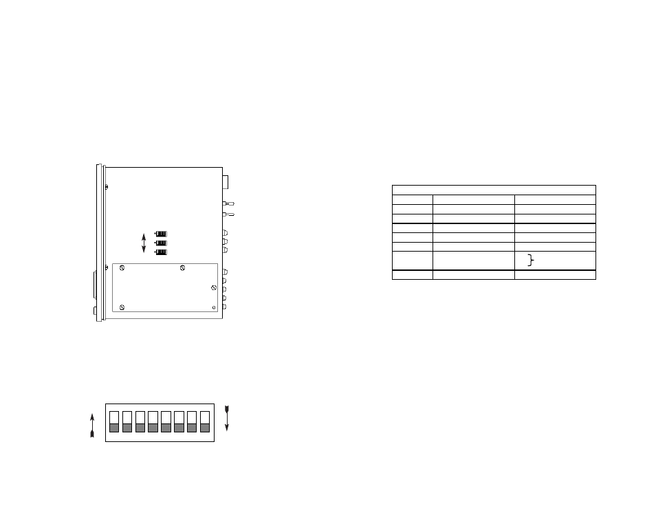
The 24 external switches are grouped into three eight-switch sets,
and are externally accessible from the underside of the Model 1094A
(See Figure 1).
The three sets of DIP switches on the underside of the Model
1094A will be referred to as S1, S2, and S3. As Figure 2 shows, the
orientation of all DIP switches is the same with respect to “ON” and
“OFF” positions.
5
Figure 2. Close Up of Configuration Switches (all sets are identical in appearance)
Figure 1. Underside of Model 1094A, Showing Location of DIP Switches
Front
Back
On
S3
S2
S1
Off
3.1.1 Configuration DIP Switch Set “S1” - Reserved Switches
All Switches in Switch S1 are reserved for future use. These
switches should remain in the On position.
3.1.2 Configuration DIP Switch Set “S2”
The configuration switches on S2 allow you to specify the Clocking
Mode and response to DTE Loop Enable. Default settings of S2 are
shown in the table below.
Switch S2-1, S2-2, S2-3, S2-4, and S-5: Reserved for Future
Use and Should Remain in the Off Position.
6
S2 SUMMARY TABLE
Position
Function
Factory Default
S2-1
Reserved
Off
S2-2
Reserved
Off
S2-3
Reserved
Off
S2-4
Reserved
Off
S2-5
Reserved
Off
S2-6
Clock Mode
On Receive
S2-7
Clock Mode
Off Recovered Clock
S2-8
Enable Loop from DTE Off Disable
1
2
3
4
5
6
7
8
ON
OFF
ON