Nic card settings, Table 9: nic default settings – Panduit PN380 User Manual
Page 18
PANDUIT DPoE Power System User’s Guide
Issue 1.0
Part Number: PN380
This following information is only applicable to chasses with NIC cards.
The NIC card can be connected via a standard straight through RJ45 patch cord (such as PANDUIT part
number UTPCH3 or UTPSP3), through a hub or router, or via a crossover cord for direct connection.
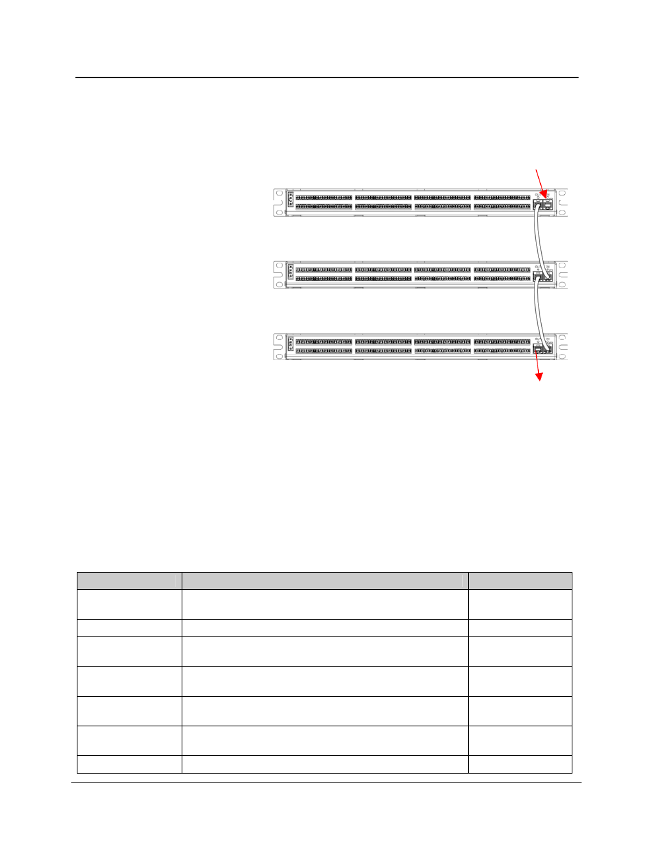
Additionally, the NIC card can be
connected to the daisy chain of
management connections used for
the installed DPoE Power Patch
Panels using a straight through
RJ45 patch cord. Connect the NIC
to the OUT management port on the
last DPoE Panel in the chain.
From
Network
To DPoE Power
System
Figure 12: Connecting the NIC Card to the DPoE Power Patch Panel
Management Port
Once a connection is made, connect to the DPoE Power System EMS Webpage via IPSetup.exe on the
CD provided with the chassis (DPoEPWRCM only). The NIC card will also work with Telnet or SNMP.
NIC Card Settings
The NIC card comes equipped with the following default settings:
Table 9: NIC Default Settings
Parameter
Description
Default Setting
Float Voltage
The voltage to which the rectifiers will regulate the plant
during float mode.
54 VDC
Rect CL Enable
Enables the system current limit feature.
Disabled
Rect CL Setpoint
The controller will limit the current of the rectifiers to this
value.
200 A
HVSD Setpoint
The controller will shut down the rectifiers if the plant
voltage exceeds this setpoint.
58 VDC
HVA Setpoint
The controller will issue a high voltage alarm if the plant
voltage exceeds this setpoint.
57 VDC
BD Alarm
The controller will issue a battery-on-discharge alarm if
the plant voltage falls below this setpoint.
48 VDC
BD TEST status
Enables or disables the battery test.
Disabled
13