0 changing components – Baxi Potterton BBU 15 HE User Manual
Page 31
31
© Baxi Heating UK Ltd 2009
10.0 Changing Components
10.8
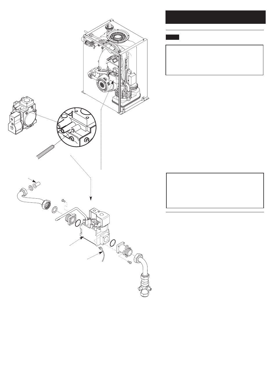
Gas Valve (Fig. 51)
IMPORTANT: After replacing the valve the CO
2
must be
checked and adjusted as detailed in Section 11.0 Setting
the Gas Valve. Only change the valve if a suitable
calibrated combustion analyser is available, operated by a
competent person - see Section 9.1
1. Disconnect the plug and earth wire from the gas valve and
remove the sensing pipe from between the valve and fan
outlet.
2. Remove the gas feed pipe and washers, and extract the
injector from the gas/air inlet manifold.
3. Undo the nut on the pipe from the gas cock to the valve
inlet adaptor, and remove the screws securing the adaptor to
the boiler side panel.
4. Remove the valve complete with the inlet and outlet
adaptors, and the seal on the inner face of the side panel.
Transfer the adaptors to the new valve, using new ‘O’ rings if
necessary.
5. Replace in reverse order of dismantling, using the screws
previously removed. Examine all sealing gaskets and washers
and replace if necessary.
NOTE: To assist the boiler to light prior to final setting,
use a suitable hexagon key to wind out the Gas/Air
adjustment screw until it is flush with the valve body, then
turn the screw 4 full turns clockwise (Fig. 51). If the boiler
will not light, or the correct CO
2
cannot be achieved
contact the ‘heateam’ technical helpline.
PCB Control Box
removed for clarity
Gas Valve
Earth Wire
Injector
Fig. 51