Baxi Potterton Solar User Manual
Page 6
Potterton Solar - Solar Thermal Domestic Hot Water System
6
2.0
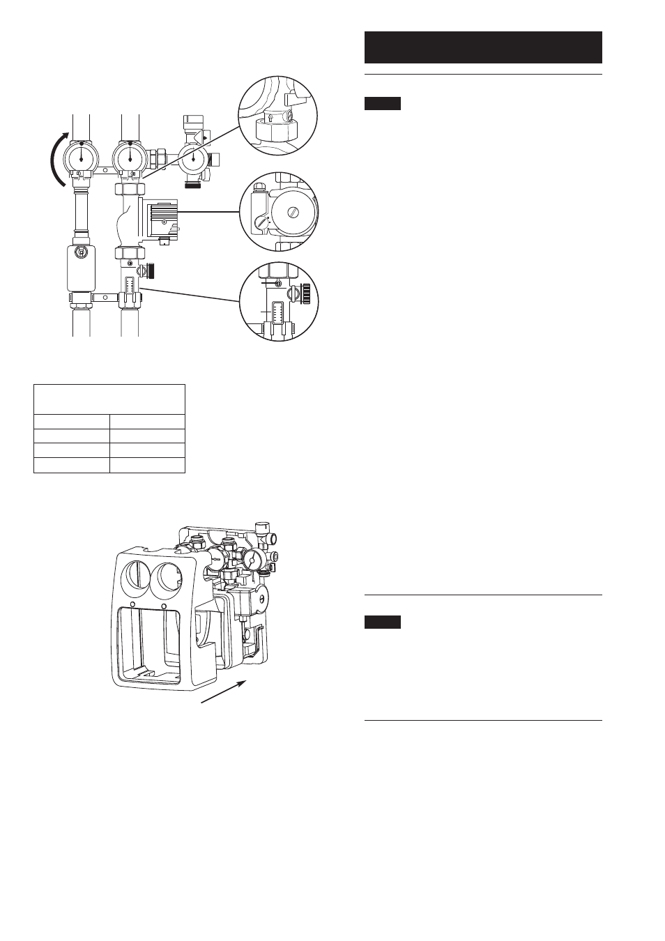
Commissioning of hydraulic station
2.4
Checking and adjusting the flow rate
Adjust the flow rate when the system is cold (20°C)
(see Fig. 5).
The flow rate should be adjusted to give the optimum
flow rate depending on the number and type of
collector panels connected.
Turn the slot of the adjusting screw (Fig. 5 Item 1) below
the return temperature gauge horizontally to close the
non-return valve.
Turn the l.h. isolating valve with integral thermometer in
the flow (Fig. 5 Item 2) as far as it will go in the direction
indicated by the arrow to close the non-return valve (dot
on bezel on top).
Turn the slot of the adjusting screw (Fig. 5 Item 3) in the
return vertically to open the flow limiter on the flow
meter (Fig. 5 Item 4).
Manually operate the solar pump (see section 3.1.7).
Set the solar pump switch (Fig. 5 Item 5) so that the
required flow rate is achieved or exceeded with the
lowest possible setting.The flow limiter adjusting screw
(Fig. 5 Item 3) can be used to fine-tune the flow rate.
Depending on the number and type of collectors installed,
set the required flow rate from table (See Table 1).
The float in the flow meter will indicate the circulation
flow rate through the flow meter sight glass.
Adjust screw of the flow limiter (Fig. 5 Item 3) with a
screwdriver, until the upper edge of the float in the sight
glass indicates the required flow rate.
Set manual pump operation to off.
2.5
Installation of the thermal insulation
Refit the controller mounting moulding (Fig. 6 Item 1)
onto the rear moulding.
Push the front thermal insulation (Fig. 6 Item 2) against
the rear thermal insulation section (Fig. 6 Item 3) until it
clips into place.
Flow rate
(when system is cold)
Collectors
l/min
1
approx. 2
2
approx. 4
3
approx. 6
Fig. 5
Fig. 6
2
5
3
4
1
2
3
1
Table 1