Connect to the console, Make the link connection(s) – Perle Systems 1700 User Manual
Page 10
Applications
4
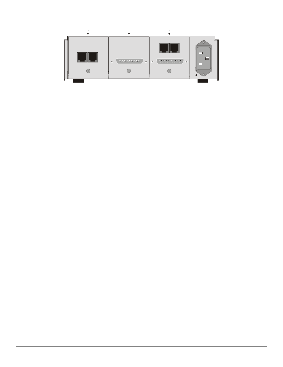
CONSOLE
10/100 BT LAN
MDI-X MDI
LAN/Console module
Power connector
RS-232/V.24
LAN 2 module
Link 2 module
10 BT LAN
MDI-X MDI
Figure 1-4 Rear View of the P1730 with Dual LAN connections and a single WAN
module
Connect to the Console
Connection to the bridge/router operator’s console is made through the DB25 connector
labeled CONSOLE on the back of the bridge/router.
Connect the console port of the Router to a computer running an asynchronous
communication package or a standard asynchronous terminal. The bridge/router supports
autobaud rates at 1200, 2400, 9600, 19,200, 38,400 or 57,600 bps. Both the bridge/router
and the bridged network are configured through the use of “hotkey” Menus.
Make the Link Connection(s)
By default the links are configured as permanent DTE interfaces. The clocking for each link
will be provided by the DCE device connected to each link.
The V.35 link modules require interface converters that convert from a DB25 connector to
a male 34-pin (V.35) connector used for the V.35 interface. Be sure to secure the cable
connector(s) to the bridge/router and the communications equipment with the connector
screws to prevent accidental disconnection.
The CSU/DSU module uses a RJ-48S connector to interface with the digital data service.
G.703 modules use a standard BNC connector with a 75 ohm cable.
The ISDN-ST interface module of the ISDN Router provides a RJ-45 connector to connect
to the RJ-45 connector of the NT1 provided with your ISDN service.
The ISDN-U interface module of the ISDN Router provides an integrated NT1 with a RJ-
45 connector to connect directly with your ISDN service.
Pinouts for the WAN connectors are listed in Appendix D of this manual.