Mounting – Planar LC1502R User Manual
Page 11
LC1502R User’s Guide
(020-0315-02B)
11
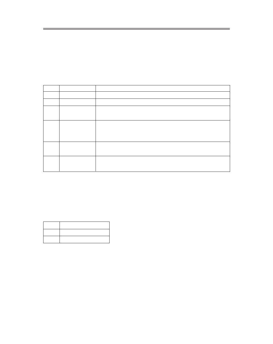
3. External Dimming Connector
Connector type: Molex Micro Fit 3.0
Mating connector: Molex 43025-0600 (housing) and Molex
43030 (terminals)
External Dimming Connector Pin Configuration and Description
Pin
Name
Description
1
Ground
Electrical ground
2
Reserved
For factory use only, leave unconnected
3
DIM_Input
0-5V analog input for external dimming, connect to wiper of
dimming pot if used
4
/Ext_DIM,
Input to determine brightness control mode; has 10k pull up to +5V
Logic high (or unconnected) = Automatic Brightness Control mode
Logic low = Manual Brightness Control mode
5
Ground
Electrical ground; connect to lower leg of dimming potentiometer
if used
6
Vref
+5V reference voltage output with 470 ohm series resistance;
connect to upper leg of dimming potentiometer if used
4. Cooling Kit Power Output Connector
Note: There is no need to connect to this connector. Information is shown for reference only. If a
Cooling Kit option is ordered, the required cooling kit power cable will be installed at the factory.
Optional Cooling Kit Pin Configuration
Pin
Description
1
Switched Return
2
+12V output
Mounting
M4 threaded holes are provided in the sides of the monitor housing for mounting purposes. The
blind holes will accommodate 10 mm long screws. See the mechanical outline drawing 076-0579-xx
at www.planar.com/support for details. Planar does not supply mounting fasteners.