Configuration dip switch set “s1, Switch s1-1: co/cp, Co/cp configuration – Patton electronic 1088/K User Manual
Page 8: Switch s1-1: co/cp co/cp configuration
8
Configuration DIP Switch Set “S1”
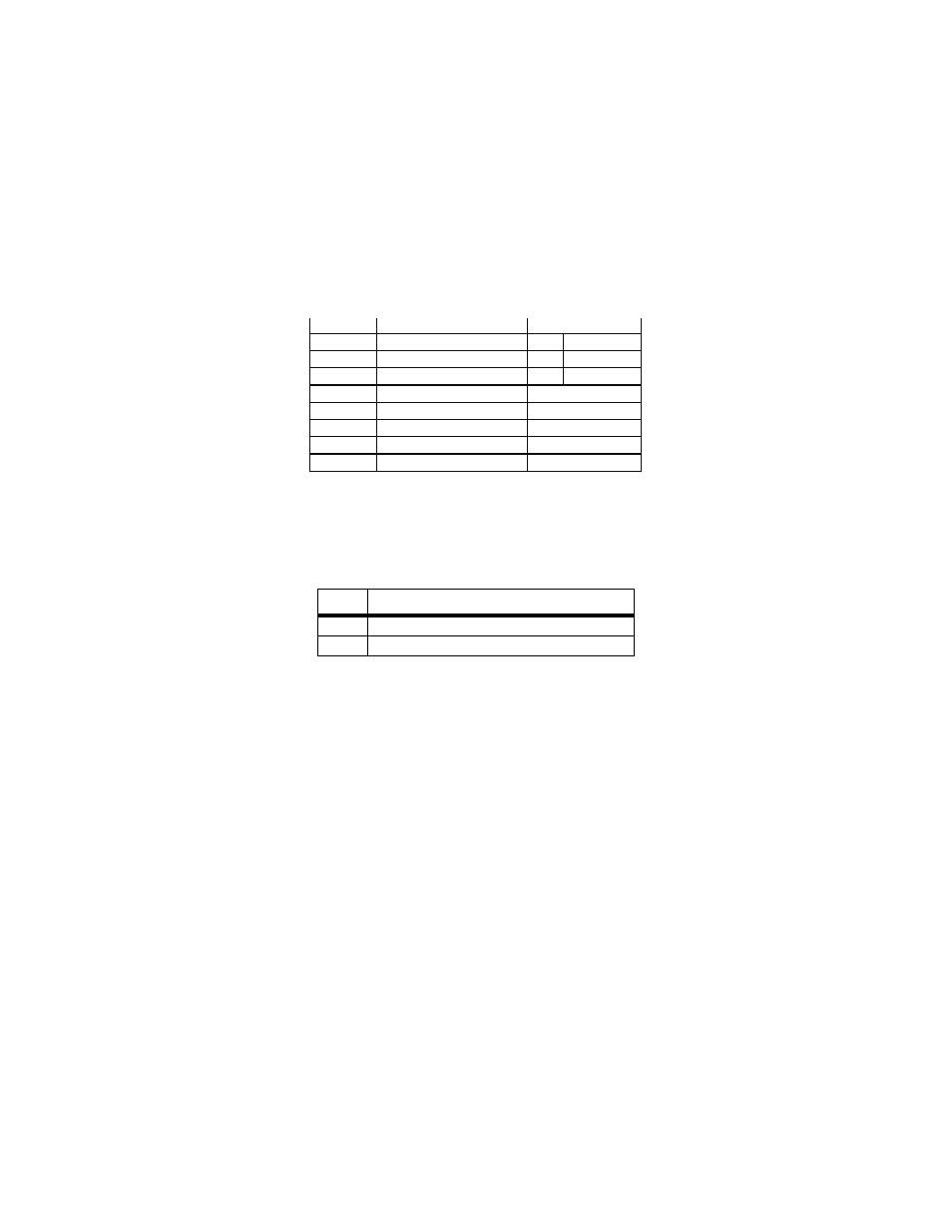
Switches S1-1 through S1-8 may be used to configure CO/CP operation,
line framing and coding, CRC-4 operation, and DTE initiated loop diag-
nostics. Default settings of S1 switches are shown in Table 1.
Table 1:
S1 Summary Table
Switch S1-1: CO/CP.
Use Switch S1-1 configure the CO (located at the
Central Office or or G.703/G.704 demarcation point) or CP (located at
the Customer Premises) mode of the 1088/K.
CO/CP Configuration.
The Model 1088/K does not use clock mode set-
tings as described in other Patton mDSL products. Instead, the Model
1088/K will always recover the clocking from the G.703/4 network and
use this clock to send data across the DSL span to the remote DSL
modem, which will use the incoming to send data out to G.703/4 net-
work. Therefore, one unit must be set for CO mode (located at the G.703
demarcation), and the other unit must be set for CP mode (located at the
customer premises). This type of clocking method was employed for two
reasons:
• To allow two independent networks to use the modems as indepen-
dent clocking paths.
• To allow the user to independently specify the timing source for the
network based on external equipment.
CO/CP and Using the 1088/K with other Patton mDSL modems
Other Patton mDSL modems allow the option of specifying the clock
mode, but not the CO/CP designation. This is already done internally
S1-1
CO/CP Mode
Off
CO = located at the Central Office
On
CP = located at the Customer Premises
Position
Function
S1-1
CO/CP Setting
On
CP Mode
S1-2
Line Coding
Off
HDB3
S1-3
CRC-4 Enable
Off
Disabled
S1-4
Reserved
Off
S1-5
Reserved
On
S1-6
Reserved
Off
S1-7
Reserved
On
S1-8
Reserved
Off
Factory Default