4 loops and patterns, Loops and patterns, 21 symbol indicators – Patton electronic 1088/K User Manual
Page 21
21
Symbol Indicators
5.4 LOOPS AND PATTERNS
The following section describes the Test Modes used in the Model 1088. At
the bottom of each Test Mode, a figure is included to show the data path.
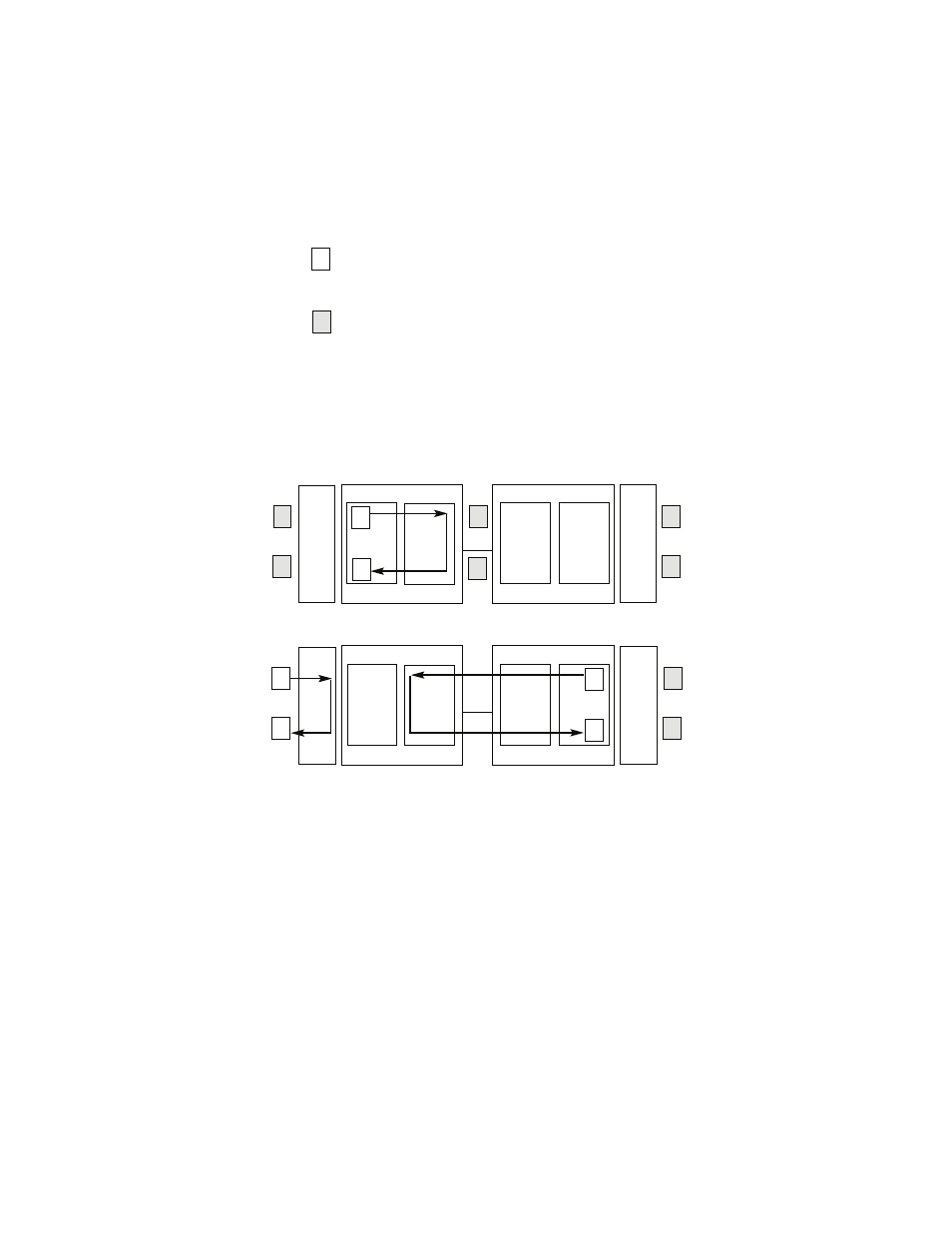
Figure 12.
Block Diagram Local Loop Mode 1
Figure 13.
Block Diagram Local Loop Mode 2
Local Loop
There are two different modes of operation for a Local Loop
depending on the status of the units at the time that the Local Loop
is initiated. If the units are not in linked (NS LED on) and the Local
Loop is initiated, either by the front panel switch or the DTE inter-
face, the unit will enter mode 1. If the units are linked, NS LED off,
then the unit will enter a mode 2 Local Loop.
A Mode 1 Local Loop is shown in Figure 12. When the Local Loop
is initiated, either by the front panel switch or the DTE interface, the
loop will be activated within the local Processor. The data present
at the local DTE interface will be looped back to the local DTE by
the Loop Control block within the Processor. Any data present on
This symbol designates the origination or the
termination of a data path. The direction of the
arrow connected distinguish the two data paths.
This symbol designates an invalid data path. If
there is data present it should be ignored.
Pattern
Gen/Det
Loop
Contr
ol
Loop
Contro
l
Pattern
Gen/Det
Processor
Processor
Framer
Framer
Line
Pattern
Gen/Det
Loop
Contr
ol
Loop
Contro
l
Pattern
Gen/Det
Processor
Processor
Framer
Framer
Line