Patton electronic 1088/K User Manual
Page 24
24
before the completion of the termination phase the switch will be
ignored until it is placed back into the normal position.
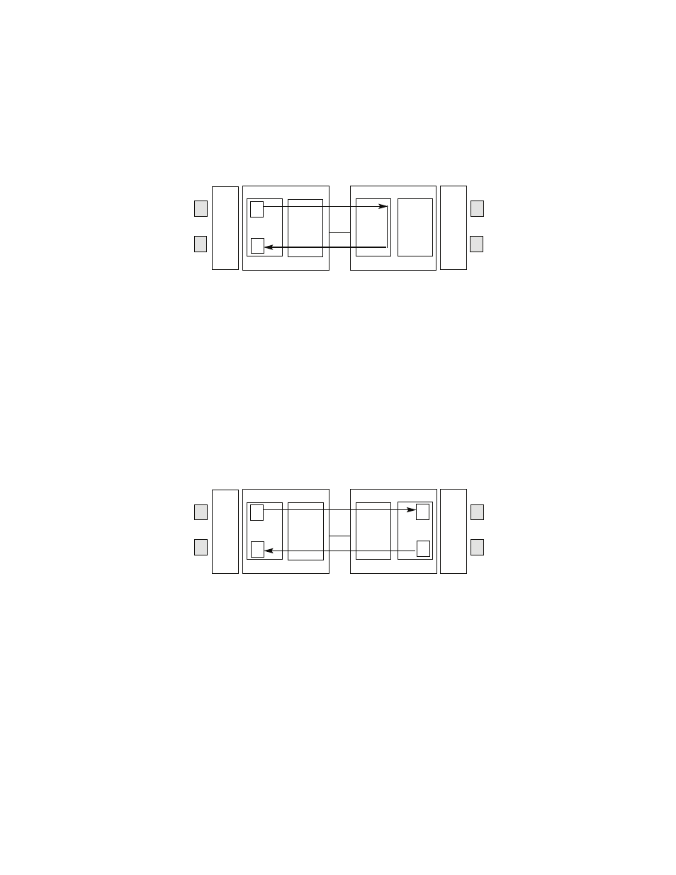
Figure 17. Block Remote Loop with 511/511E
Remote Digital Loop with 511/511E
The Remote Digital Loop with 511/511E is shown above. After
RDL is established the Remote units' Restart Timer is set to one
minute. This has been done because when the 511/511E genera-
tor is started on the local unit, the Remote framer begins seeing
unframed packets. The Remote unit can not distinguish the 511/
511E pattern from the line being disconnected so the Restart
Timer has been lengthened to allow the pattern generator to func-
tion. Once the 511/511E test is started, the Local unit changes its'
Restart Timer to one minute. The pattern originates within the Pro-
cessor and is sent to the Remote unit. It is then looped back to the
Local unit where it is evaluated for errors. After 45 seconds, the
Pattern Generator will timeout and stops sending the pattern. The
ER led will begin blinking until the user turns off the 511/511E
switch.
Figure 18. Block Diagram DataMode with 511/511E
Data Mode with 511/511E Pattern Generators
When the units enter DataMode it is possible to turn on the 511/
511E pattern generators on both ends of the link. Once a 511/
511E pattern is selected on one end of the link, the pattern genera-
tor will begin transmitting unframed 511/511E through the line to
the Remote end. A possible problem with this test can occur due to
the Restart procedure. Once the Local 511/511E is turned on, the
Remote unit begins receiving an unframed 511 pattern. If the
Remote unit does not turn on the 511/511E-pattern generator
within 4 seconds, the Remote unit will Restart and enter the Start-
Pattern
Gen/Det
Loop
Contr
ol
Loop
Contro
l
Pattern
Gen/Det
Processor
Processor
Framer
Framer
Line
Pattern
Gen/Det
Loop
Contr
ol
Loop
Contro
l
Pattern
Gen/Det
Processor
Processor
Framer
Framer
Line