Plug j8, Troubleshooting and repair, Current transducer test (continued) – Lincoln Electric INVERTEC SVM158-A User Manual
Page 88
TROUBLESHOOTING AND REPAIR
CURRENT TRANSDUCER TEST (continued)
F-38
F-38
V350-PRO
TEST PROCEDURE
1.
Remove input power to the V350-PRO.
2.
Using the 5/16” nut driver, remove the case
wraparound cover.
3.
Perform the Input Capacitor Discharge
Procedure.
4.
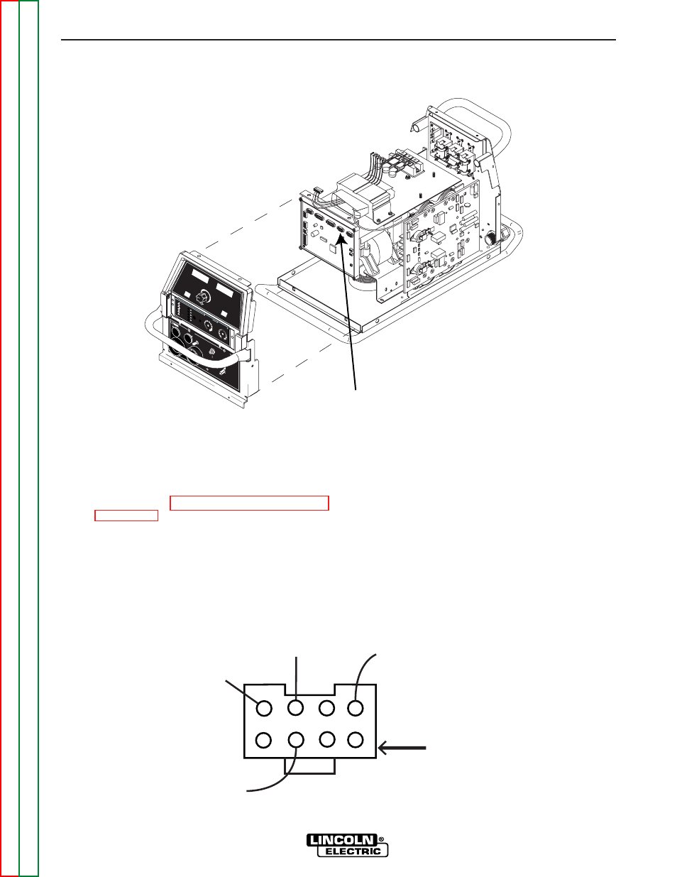
Locate plug J8 on the control board. Do not
remove the plug from the P.C. Board.
5.
Apply the correct input power to the V350-
PRO.
6.
Check for the correct DC supply voltages to
the current transducer at plug J8. See Figure
F.11.
A. Pin 2 (lead 802+) to pin 6 (lead 806-)
should read +15 VDC.
B. Pin 4 (lead 804+) to pin 6 (lead 806-)
should read -15 VDC.
7.
If either of the supply voltages are low or miss-
ing, the control board may be faulty.
FIGURE F.10 Metal Plate Removal & Plug J8 Location
802
801
804
806
Plug J8
FIGURE F.11. Plug J8 Viewed From Lead Side of Plug
WA
RNING
REMOTE
POWER
OFF
ON
A
AMPS
A
V
VOL
TS
W
ELD
TER
MIN
ALS
SE
LE
CT
OUTPUT
HO
T S
TA
RT
AR
C C
ON
TR
OL
-4
+4
+2
-2
0
-6
+6
-10
SOFT
CRISP
+10
-8
+8
5
4
3
2
1
0
6
10
9
8
7
SELEC
T
CC
-STICK 7018
CC-STICK 6010
TIG
G
TAW
CV
-W
IR
E
CV
-FLU
X CO
RED
Plug J8