Troubleshooting & repair, Caution, Control board removal and replacement (continued) – Lincoln Electric INVERTEC SVM158-A User Manual
Page 103
Observe static precautions detailed in PC
Board Troubleshooting Procedures at the
beginning of this section.
6. Using a flat head screwdriver remove the two
screws and their washers from above and below
the input power switch. See Figure F.17.
7. Using a phillips head screwdriver remove the four
screws from around the two welder output termi-
nals on the front of the machine. See Figure F.17.
8. The front of the machine may now gently be pulled
forward to gain access to the display Board. Note:
The front of the machine cannot be removed com-
pletely, only pulled forward a few inches.
9. Beginning at the right side of the control board
remove plugs J10A and J10B. Note: Be sure to
label each plugs position upon removal. See
Figure F.18.
10. Working your way across the top of the board
from right to left, label and remove plugs #J9, #J8,
#J7, #J6, and #J5. See Figure F.18.
11. Working your way down the left side of the board,
label and remove plugs #J4 and #J3. See Figure
F.18.
CAUTION
V350-PRO
TROUBLESHOOTING & REPAIR
F-53
F-53
W
ARNING
REMOTE
POWER
OFF
ON
A
AMPS
A
V
VOL
TS
WELD
TERMINALS
SELECT
OUTPUT
HOT
S
TAR
T
ARC
C
ONTROL
-4
+4
+2
-2
0
-6
+6
-10
SOFT
CRISP
+10
-8
+8
5
4
3
2
1
0
6
10
9
8
7
SE
LE
CT
CC
-STIC
K 7018
CC
-STIC
K 6
010
TIG G
TA
W
CV
-W
IR
E
CV-
FLU
X CO
RE
D
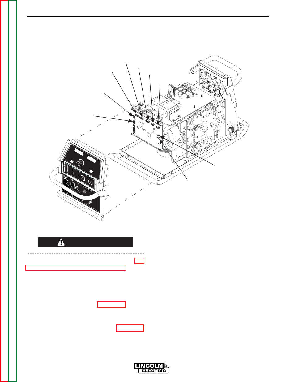
J3
J4
J5
J6
J7
J8
J9
J10A
J10B
FIGURE F.18. - CONTROL BOARD ALL PLUG LOCATIONS
CONTROL BOARD REMOVAL AND REPLACEMENT (continued)