Theory of operation, Output rectifier and choke – Lincoln Electric INVERTEC SVM158-A User Manual
Page 47
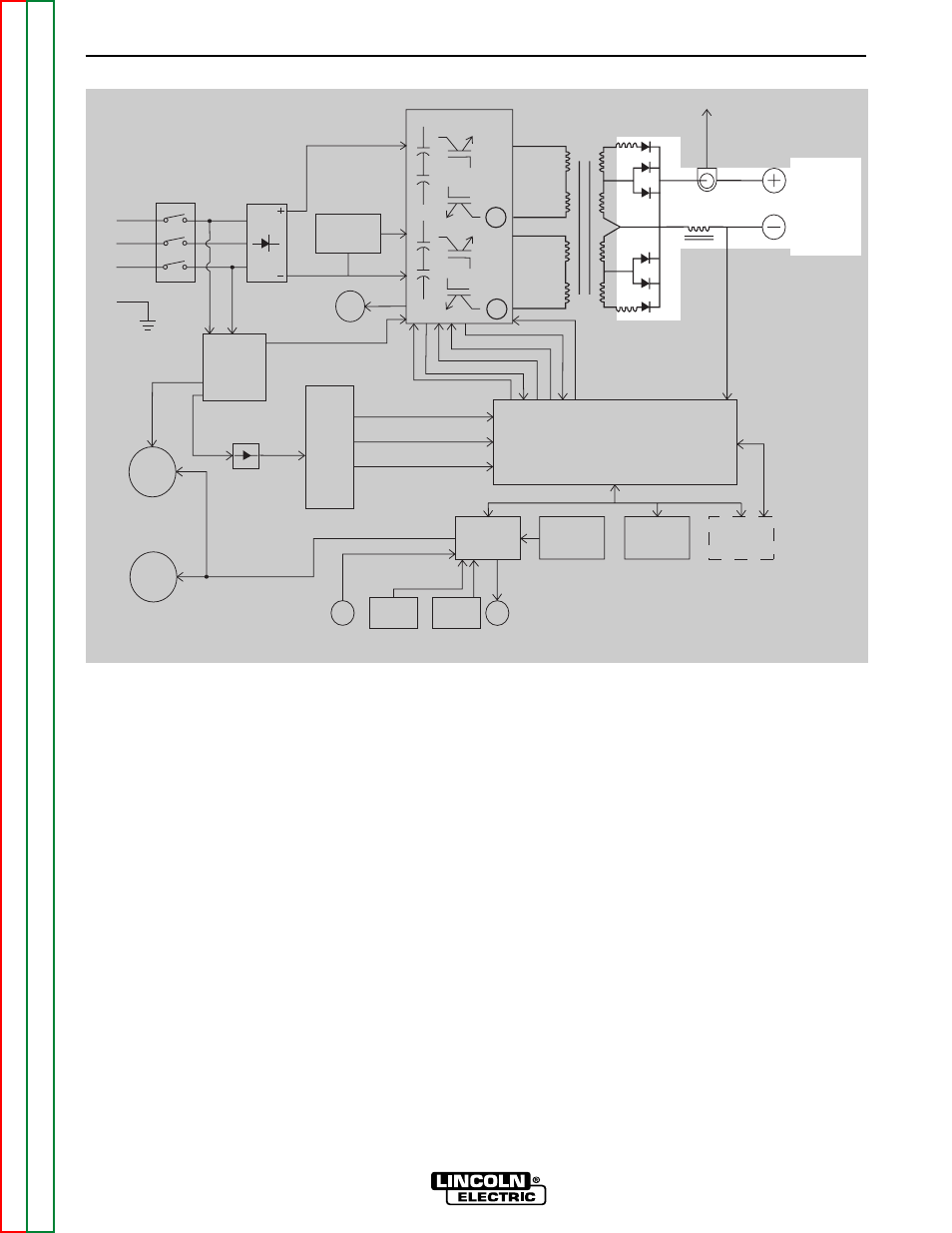
OUTPUT RECTIFIER AND CHOKE
The output rectifier receives the AC output from the
main transformer secondary and rectifies it to a DC
voltage level. Since the output choke is in series with
the negative leg of the output rectifier and also in
series with the welding load, a filtered DC output is
applied to the machine’s output terminals.
THEORY OF OPERATION
E-5
E-5
V350-PRO
FIGURE E.5 – OUTPUT RECTIFIER AND CHOKE
Remote
Board
Mode
Panel
Display
Panel
Control Board
Choke
Positive
Output
Terminal
Negative
Output
Terminal
To Control
Board
Current
F
eedbac
k
Reconnect
Switch
Output V
oltage
Sense
Input switch
Input
Rectifier
Auxiliary
Transformer
Fan
Power
Board
14 Pin
Amphenol
6 Pin
Amphenol
Remote Control & Trigger
RS232 Supply +5VDC
SPI Supply +15VDC +5VDC
Machine Control Supply
+15VDC, -15VDC, +5VDC
40VDC
28VAC
24VAC
115VAC, 42VAC
Main Switch Board
115VAC Fan Supply
Optional Solenoid
SPI Communications & +15VDC, +5VDC Supply
F
an Control
V/F Capacitor Feedback (2)
Soft Start Control
Input Relay Control
Primary Current Feedback
IGBT Dr
iv
e Signal
Primary
Current
Sensor
Primary
Current
Sensor
Output
Potentiometer
Output
Control
Weld
Terminals
Advanced
Process
Panel
RS232
12 VDC
(Not used if APP
is in place)
NOTE: Unshaded areas of Block Logic Diagram are the subject of discussion.