Input rectifier, Troubleshooting & repair, Procedure – Lincoln Electric INVERTEC SVM158-A User Manual
Page 130: F-80, Figure f.36. – input rectifier location
PROCEDURE
1. Remove input power to the V350-PRO.
2. Using a 5/16” nut driver remove the case
wraparound cover.
3. Perform the Input Filter Capacitor Discharge
Procedure detailed earlier in this section.
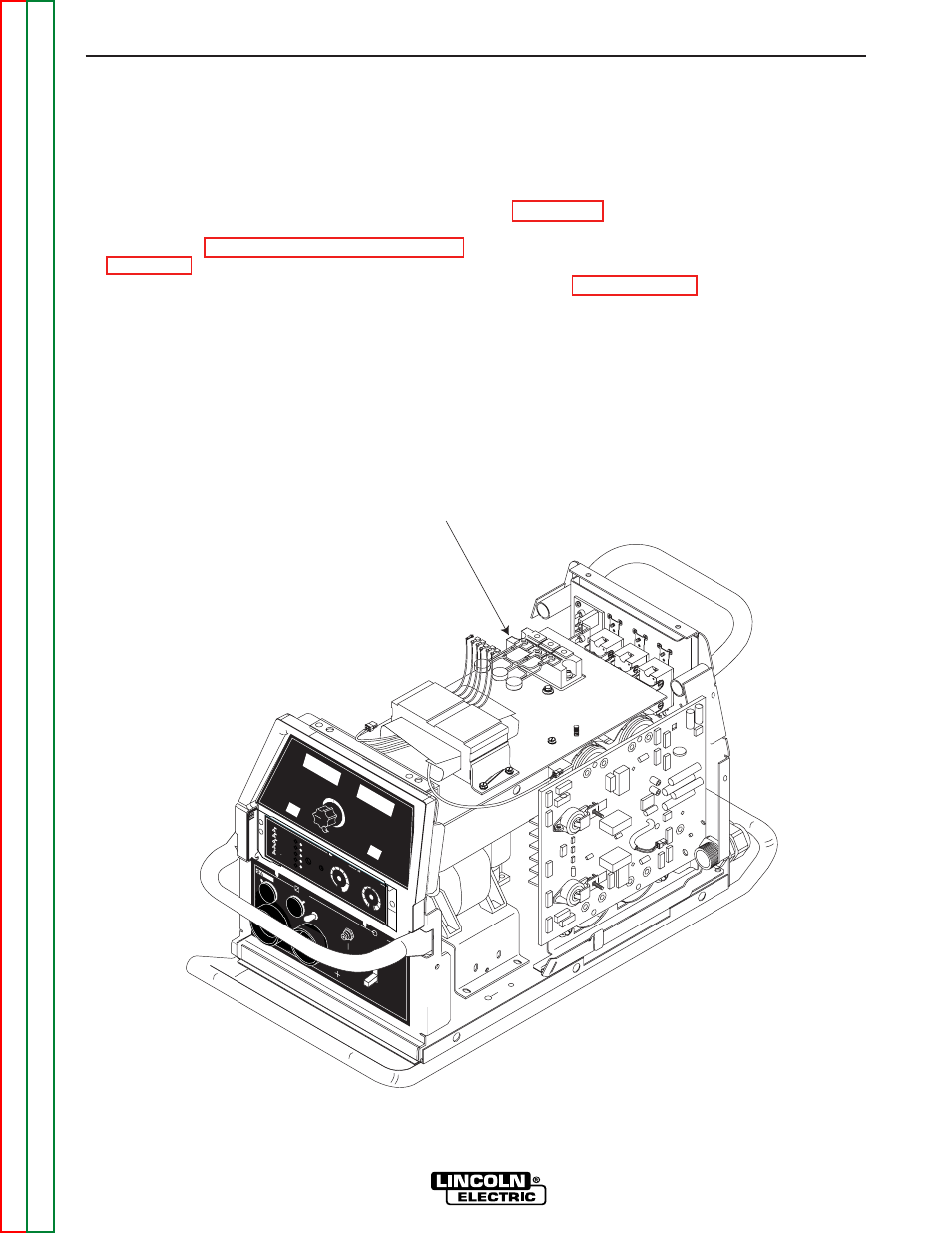
4. Locate the input rectifier. See figure F.36.
5. Carefully remove the silicon sealant insulating the
six input rectifier terminals.
6. Remove the six screws from the terminals using a
flathead screwdriver. Carefully note the position of
all leads and their positions upon removal. See
Figure F.37.
7. Using a 3/16”in. allen wrench remove the two
mounting screws and washers from the input
bridge. See Figure F.37.
8. Remove the input bridge.
TROUBLESHOOTING & REPAIR
INPUT RECTIFIER REMOVAL AND REPLACEMENT (continued)
F-80
F-80
V350-PRO
W
ARNING
REMOTE
POWER
OFF
ON
A
AMPS
A
V
VOL
TS
WELD
TERM
IN
ALS
SELECT
OUTPUT
HOT
S
TAR
T
ARC
C
ONTROL
-4
+4
+2
-2
0
-6
+6
-10
SOFT
CRISP
+10
-8
+8
5
4
3
2
1
0
6
10
9
8
7
SELECT
CC
-S
TIC
K 7
018
CC
-S
TIC
K 6
010
TIG G
TAW
CV
-WIR
E
CV
-F
LUX
C
ORED
INPUT
RECTIFIER
FIGURE F.36. – INPUT RECTIFIER LOCATION