Troubleshooting – Lochinvar EnergyRite ER402 User Manual
Page 25
Service Manual
25
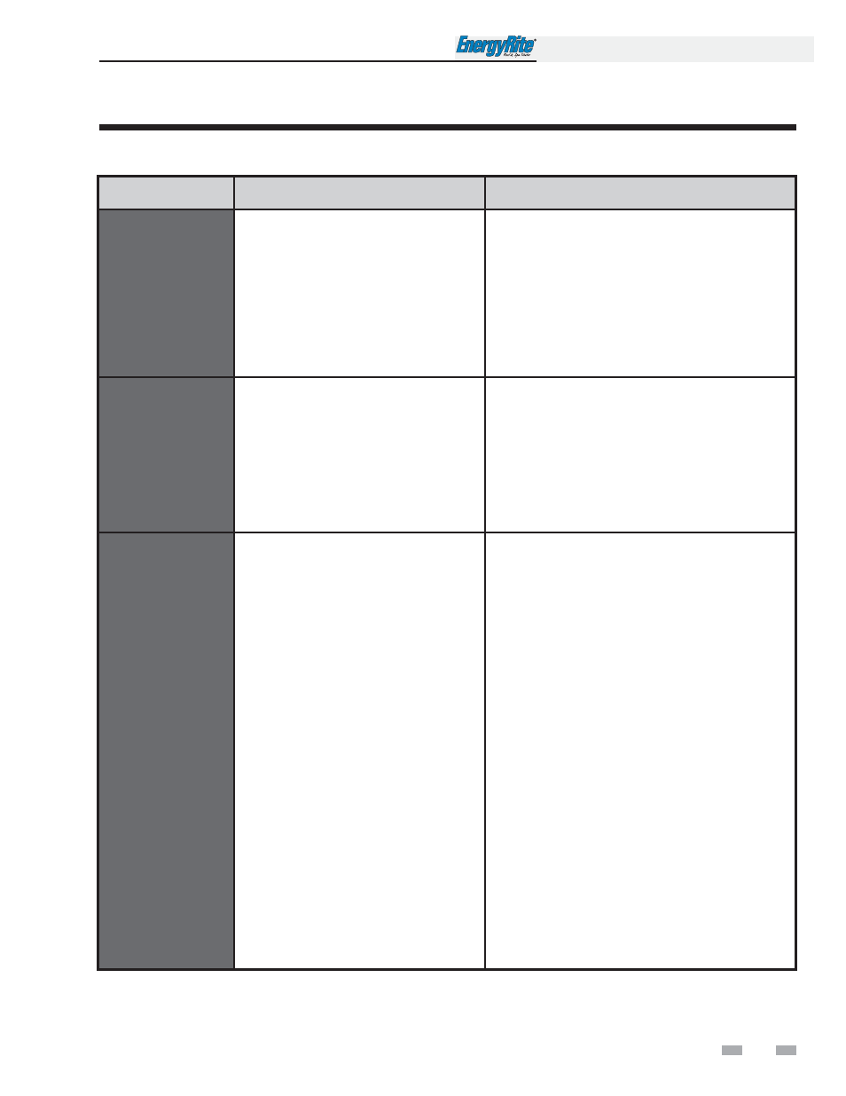
Table 3D Troubleshooting Chart - Fault Messages Displayed on Pool Heater Interface
F
FA
AU
UL
LT
T
D
DE
ES
SC
CR
RIIP
PT
TIIO
ON
N
C
CO
OR
RR
RE
EC
CT
TIIV
VE
E A
AC
CT
TIIO
ON
N
AUX Device 1
Open
The field supplied safety wired into AUX
Device 1 has opened. This will most
commonly be a flow switch or low water
cutoff.
• Check pool heater pump operation on a call for heat.
• Check for closed valves or obstructions in the pool
heater piping.
• Verify system is full of water and all air has been
purged from the system.
• Check for loose or misplaced jumpers if flow switch
or LWCO is not installed.
• If other safety device, ensure device is working
properly and conditions are accurate.
Flame
Sequence
(will require a manual
reset once the condition
has been corrected.
Press the RESET button
on the display to reset.)
The flame detector circuit is seeing a flame
signal while no flame is present.
• Check supply voltage for proper polarity.
• Check external wiring for voltage feedback.
• Check the flame rod and make sure it is clean.
• Check the internal wiring for bad connections.
• Replace main control board.
Ignition Failure
(will require a manual
reset once the condition
has been corrected.
Press the RESET button
on the display to reset.)
The pool heater has failed to prove main
burner ignition after four (4) attempts.
• Check for proper electrical grounding of the pool
heater.
• Check incoming supply gas pressure. Natural gas
pressures should be between 4.0 - 14 inches w.c.
and LP gas pressures should be between 8.0 -
14 inches w.c. Refer to Section 6 - Gas Connections
of the EnergyRite Installation and Operation Manual
for detailed information concerning the gas supply.
• Verify that the outdoor vent cap or vent/air intake
pipes are installed correctly and that there are no
obstructions.
• Check for 24 VAC to the gas valve.
• If 24 VAC is present at the main control board, check
the wiring between the main control board and the
gas valve. Replace the wiring if necessary.
• If 24 VAC is present, check the outlet of the valve to
ensure the valve is flowing gas. With a manometer
connected to the outlet tap of the gas valve there
should be very little pressure during pre-purge.
Once the ignition begins, the pressure should jump
to around 3 inches. If this sudden change does not
happen then the valve is not opening.
• Inspect the burner. Reference page 16 of this
manual for removal and cleaning procedures.
Replace if necessary.
• Replace the main control board.
3
Troubleshooting
(continued)