Table2.3 setting jumpers, 4 completing the installation, Completing the installation – LSI U40HVD User Manual
Page 39: Setting jumpers
Completing the Installation
2-23
separate interrupts, jumper TP1 (see
) is provided to change
the interrupt routing. The following table explains the jumper settings:
2.4
Completing the Installation
Before replacing the cover on your computer, review this installation
procedure check list. This can save you effort later.
Step 1.
Replace the cabinet cover on your computer.
Step 2.
Plug in all power cords, and switch on power to all devices and
your computer.
Step 3.
Wait for your computer to boot up.
Step 4.
To change the configuration of the LSIU40HVD, see
Step 5.
Finally, refer to the PCI Storage Device Management System
SDMS 4.0 User’s Guide (or the guide for the software you plan
to use) to load the driver software for your particular operating
system.
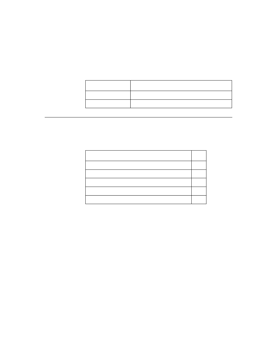
Table 2.3
Setting Jumpers
Jumper Setting
Condition
Jumper Out (default)
INTB/ is routed to INTB/ on the PCI bus
Jumper In
INTB/ is rerouted at power up to INTA/ on the PCI bus
Verify Installation Procedures
Done
Host adapter connection in PCI bus slot secure
Internal SCSI bus connections secure (pin-1 continuity)
External SCSI bus connections secure
Proper SCSI bus termination established
Unique SCSI IDs set and recorded for each device