Electrical diagrams – Lincoln Electric INVERTEC SVM101-B User Manual
Page 106
NOTE:
Lincoln Electric assumes no responsibility for liablilities resulting from board level troubleshooting. PC Board repairs will invalidate your factory warranty. Individual Printed Circuit Board Components are not available from Lincoln Electric. This information is pro-
vided for reference only. Lincoln Electric discourages board level troubleshooting and repair since it may compromise the quality of the design and may result in danger to the Machine Operator or Technician. Improper PC board repairs could result in damage to the
machine.
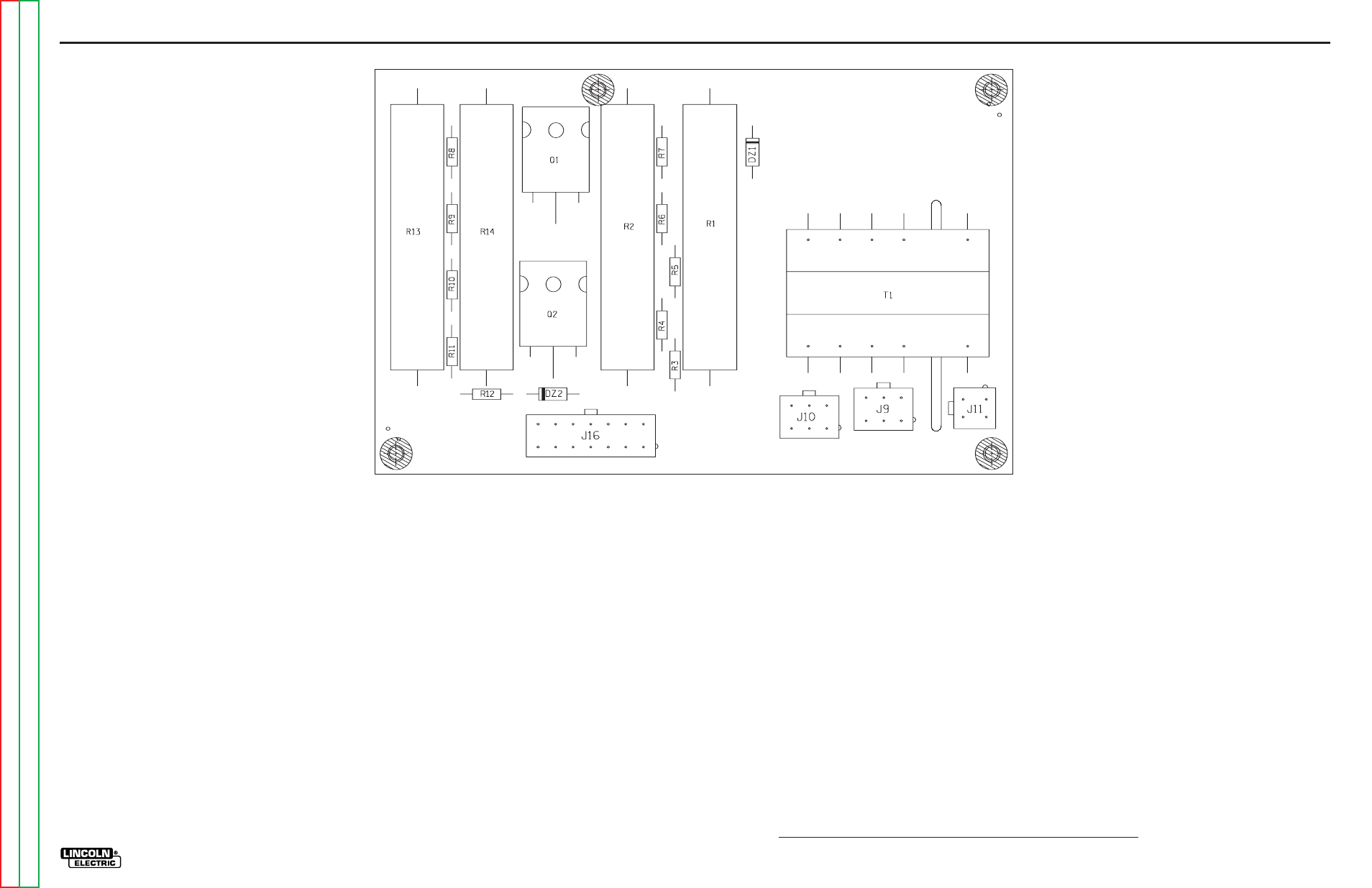
ELECTRICAL DIAGRAMS
G-14
V300-I
PC BOARD ASSEMBLY - DRIVER - (9134-[ ])
G-14
DRIVER
XXXXXXX
XXXXXXX
XXXX
XXXX
XXXXX
XXXXX
XXXX
XXXX
XXXX
XXXX
XXXX
XXXX
XXXX
XXXX
L9134
Item
Description
J11
HEADER
J9,J10
HEADER
T1
TRANSFORMER
J16
HEADER
R1,R2,R13,R14
20 WATT 250 OHM RESISTOR
DZ1,DZ2
1N4742A
Q1,Q2
FET (SS)
R7,R12
100 1/4W
R3,R4,R5,R6,R8,R9,
150K 1/4W
R10,R11