Commercial pool heaters, Installation, Continued – Lochinvar F0600187510 User Manual
Page 30: Gas manifold pressure adjustment
Commercial Pool Heaters
INSTALLATION
Continued
Gas Manifold Pressure Adjustment
IMPORTANT: The gas valves are referenced to the
fan pressurized chamber by a hose connected from
the vent of the gas valve regulator to the chamber
pressure tap located on the front inside portion of
the jacket. Reference the drawings in this section for
component and connection points for pressure
measurement. The procedure for connecting a
manometer or magnahelic must be followed to
obtain actual net manifold pressure for normal
operation. A manometer or magnahelic gauge
legible in 0.1" increments up to 10 inches w.c. is
required to check and adjust the manifold pressure.
The regulator cover screw on the gas valve must be
in place and tight at all times for the pool heater to
operate properly.
1. Remove the thumbscrew that fastens the control panel access
door and pull out the control panel.
2. Turn the power switch located in the lower left corner behind
the control panel access door to the “O” or “OFF” position.
3. Remove the top front jacket access panels to access the gas
valves.
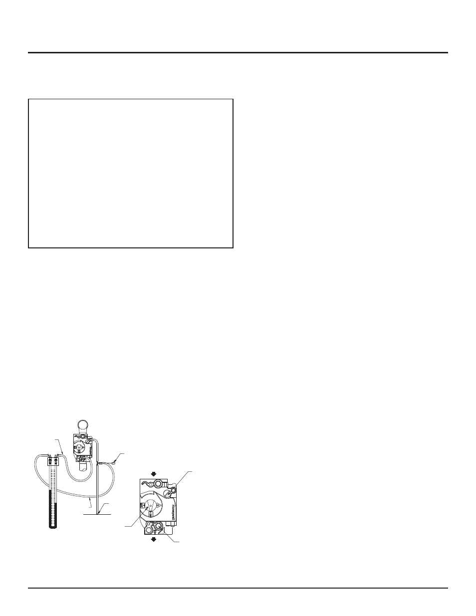
4. Locate the reference hose on the second gas valve which goes
from the vent fitting on the gas valve to a barbed fitting on the
deck of the pool heater (see Figure 31).
5. Remove the flexible cap from the barbed fitting on the “tee”
located in this line and hook one side of the manometer, or (-)
side of a magnahelic gauge, to this “tee”. Retain this cap for
future use.
INLET
OUTLET
MANOMETER
4
4
3
3
2
2
1
1
0
0
1
1
2
2
3
3
4
4
CAP
MANIFOLD
PRESSURE
CHAMBER
PRESSURE
BARBED
FITTING
GAS
VALVE
CONTROL
KNOB
PRESSURE
REGULATOR
ADJUSTMENT
(UNDER CAP SCREW)
1/8" HEX
MANIFOLD
PRESSURE
TAP
Figure 31 – Measuring Net Manifold Gas Pressure
6. Remove the 1/8" hex plug from the manifold pressure tap on
the gas valve (see Figure 31). Retain plug for future use.
7. Install a fitting in this tap that is suitable for connection of a
hose to a manometer, or (+) side of a magnahelic gauge
(see Figure 31).
8. Turn the power switch to the “I” or “ON” position.
9. Push the reset button(s) for the ignition control(s), if necessary.
10. Set the temperature control to call for heat (see Programming
Temperature Control, page 41).
11. Once the pool heater is firing the manometer/magnahelic will
reflect the Manifold Gas Pressure. Compare this reading to the
respective value in TABLE-L, page 31 for Natural or Propane
Gas.
12. If adjustment is necessary, remove the regulator cover screw on
the gas valve.
Note: If the gas valve under adjustment is located on a manifold
assembly monitored by an igniter, the pool heater may shut down
and recycle when the regulator cover screw is removed. This is
normal.
13. Turn the regulator adjustment screw “clockwise” ; to raise the
regulator gas pressure. Turn the regulator adjustment screw
“counterclockwise”; to lower the regulator gas pressure.
14. Replace the regulator cover screw and make sure it is tight for
proper operation.
15. Read the value on the manometer/magnahelic and compare it
to the values in TABLE-L.
16. Repeat this adjustment procedure for each gas valve as necessary
to adjust to the proper manifold gas pressure.
17. Remove hoses, replace and tighten plugs and caps when
complete.
18. Replace top front upper jacket access panels and control panel
door in reverse order.
19. If proper ignition and burner operation is not achieved after
checking gas supply pressure, see Cleaning and Maintenance,
page 49 for Combustion Air Fan Adjustment. Follow the
procedure to adjust the combustion air fans as necessary.
30