Installation and service manual – Lochinvar F0600187510 User Manual
Page 29
Installation and Service Manual
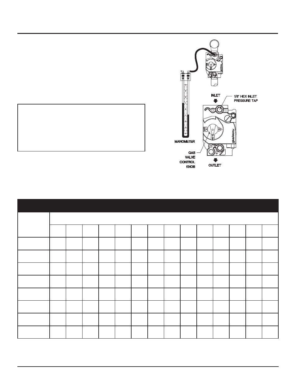
13. Remove the manometer and related fitting from the “inlet” side
of the gas valve, replace 1/8" hex plug in the gas valve and
tighten.
14. Turn on the gas supply at the manual valve, turn on L.P. gas at
the tank if required.
15. Turn the power switch to the “ON” position.
16. Turn the gas valve knobs to the “ON” position.
17. Set the temperature control to call for heat.
ƽ
WARNING: After completing any testing on the
gas system, leak test all gas connections. Apply a
soap/water solution to all gas connections while
main burners are operating. Bubbles forming
indicate a leak. Repair all leaks at once. Do not
operate this pool heater with a leak in the gas train,
valves or related piping.
Check burner performance by cycling the system while you observe
burner response. Burners should ignite promptly. Flame pattern
should be stable, see Burner Flames, page 47. Turn system off and
allow burners to cool, then cycle burners again to ensure proper
ignition and flame characteristics.
Figure 30 – Measuring Gas Supply Pressure at Combination
Gas Valve
TABLE - K
Multiple Unit Installations Gas Supply Pipe Sizing
Nominal
Iron Pipe
Size
(Inches)
Length of Pipe in Straight Feet
10
20
30
40
50
60
70
80
90
100
125
150
175
200
3/4"
369
256
205
174
155
141
128
121
113
106
95
86
79
74
1"
697
477
384
328
292
267
246
256
210
200
179
164
149
138
1 1/4"
1,400
974
789
677
595
543
502
472
441
410
369
333
308
287
1 1/2"
2,150
1,500
1,210
1,020
923
830
769
707
666
636
564
513
472
441
2"
4,100
2,820
2,260
1,950
1,720
1,560
1,440
1,330
1,250
1,180
1,100
974
871
820
2 1/2"
6,460
4,460
3,610
3,100
2,720
2,460
2,310
2,100
2,000
1,900
1,700
1,540
1,400
1,300
3"
11,200
8.900
6,400
5,400
4,870
4,410
4,000
3,800
3,540
3,300
3,000
2,720
2,500
2,340
4"
23,500 16,100 13,100 11,100 10,000
9,000
8,300
7,690
7,380
6,870
6,150
5,640
5,130
4,720
Maximum capacity of pipe in thousands of BTU’s per hour for gas pressures of 14 Inches Water Column (0.5 PSIG) or less and a total system pressure drop of 0.5
Inch Water Column (Based on NAT GAS, 1025 BTU’s per Cubic Foot of Gas and 0.60 Specific Gravity).
29