Lakeshore Learning Materials 642 User Manual
Page 42
Lake Shore Model 642 Electromagnet Power Supply User’s Manual
4-2
Operation
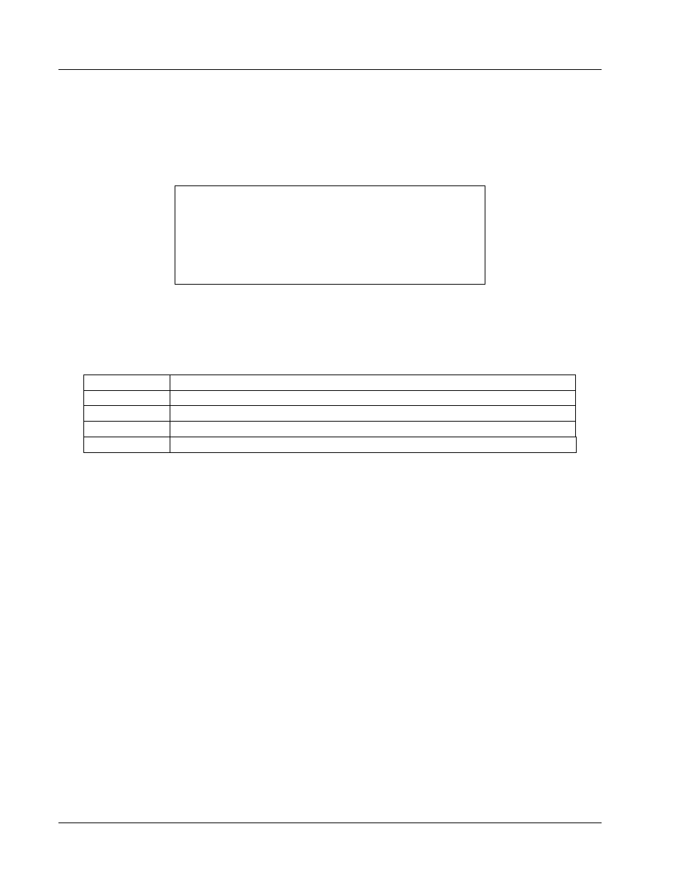
4.2 DISPLAY
DEFINITION
The Model 642 has an 8 line by 40 character vacuum fluorescent (VF) display capable of showing both text and graphic
images. The features displayed during normal operation include current measurement, voltage measurement, current
programming, ramp rate, magnet water status, internal water status, program mode, and internal temperature. Other
display configurations appear during parameter setting and data entry operations. These displays are illustrated in their
individual operation paragraphs. A typical display is shown below.
Output I Output V
+70.0000
A
+35.000
V
Set: +70.0000 A Rate:0.0001 A/s
Magnet Water: Off Pgm Mode: Internal
Int Water: Off Int Temp: 27.5 ±C
4.3 LED
ANNUNCIATORS
There are five LED annunciators on the front panel that are used to indicate the status of the instrument. These provide
easy verification of the operation of the instrument. See Figure 4-2 for LED locations.
Table 4-1. Model 642 LED Descriptions
Fault
On when a hardware fault condition exists, blinking when a soft fault condition exists.
Compliance
On when maximum compliance voltage is reached.
Power Limit
On when power in internal devices reaches the maximum limit.
Ramping
On when output current is ramping, blinking when ramp is paused.
Remote
On when instrument is in remote computer interface mode.
4.3.1 Fault
LED
The Fault LED will light whenever an error condition is encountered. It may also be accompanied by an alarm depending
on the fault. (Refer to Table 7-2 Instrument Hardware Errors, and Table 7-3 Operational Errors.)
4.3.2 Compliance
LED
The Compliance LED lights whenever the maximum output voltage is reached. This can happen when attempting to
rapidly ramp a magnet with higher than usual voltage required to overcome the magnet’s inductance. The led will go out
when the condition clears.
4.3.3 Power Limit LED
The Model 642 has a hardware power limit to protect the internal power MOSFETs. If the power supply is driving a load
which has a resistance lower than the supply’s rated minimum, the power required may be higher than the devices can
safely handle. If this happens, the power in the devices is prevented from exceeding the safe limit and the Power Limit
LED will light to alert the operator to the condition. The led will go out when the condition clears.
4.3.4 Ramping
LED
The Ramping LED lights whenever the internal control circuitry is changing the output current. When the ramp is
completed and the current is at the desired point, the LED goes out. The LED does not light when the output current is
being controlled by an external source.
4.3.5 Remote
LED
The Remote LED is lit when the Remote key has been pressed to accept remote computer programming input, or upon
receiving the first command over the IEEE bus. When the LED is lit, the main keypad is locked out. Pressing the Local
key will return the unit to the local mode and reestablish keypad functions.