Lakeshore Learning Materials 642 User Manual
Page 103
Lake Shore Model 642 Electromagnet Power Supply User’s Manual
Service
7-11
7.10 CONNECTOR
AND
CABLE DEFINITIONS
All non-power electrical connections to the rear of the Model 642 are detailed in this section.
7.10.1
Analog I/O Connector
The Analog I/O connector provides the connections for the External Programming voltage as well as Analog
representations of the current and voltage output levels. Although these inputs/outputs are electronically balanced to
minimize ground loops, the common-mode voltage should not exceed 5 V on the outputs and 2 V on the input.
1
8
9
15
Pin Name Pin Name
1
2
3
4
5
6
7
8
NC
Chassis-common
Current Program –
Chassis-common
Voltage Monitor –
Chassis-common
Current Monitor –
Chassis-common
9
10
11
12
13
14
15
NC
Chassis-common
Current Program +
Chassis-common
Voltage Monitor +
Chassis-common
Current Monitor +
Figure 7-7. ANALOG I/O Connector Details
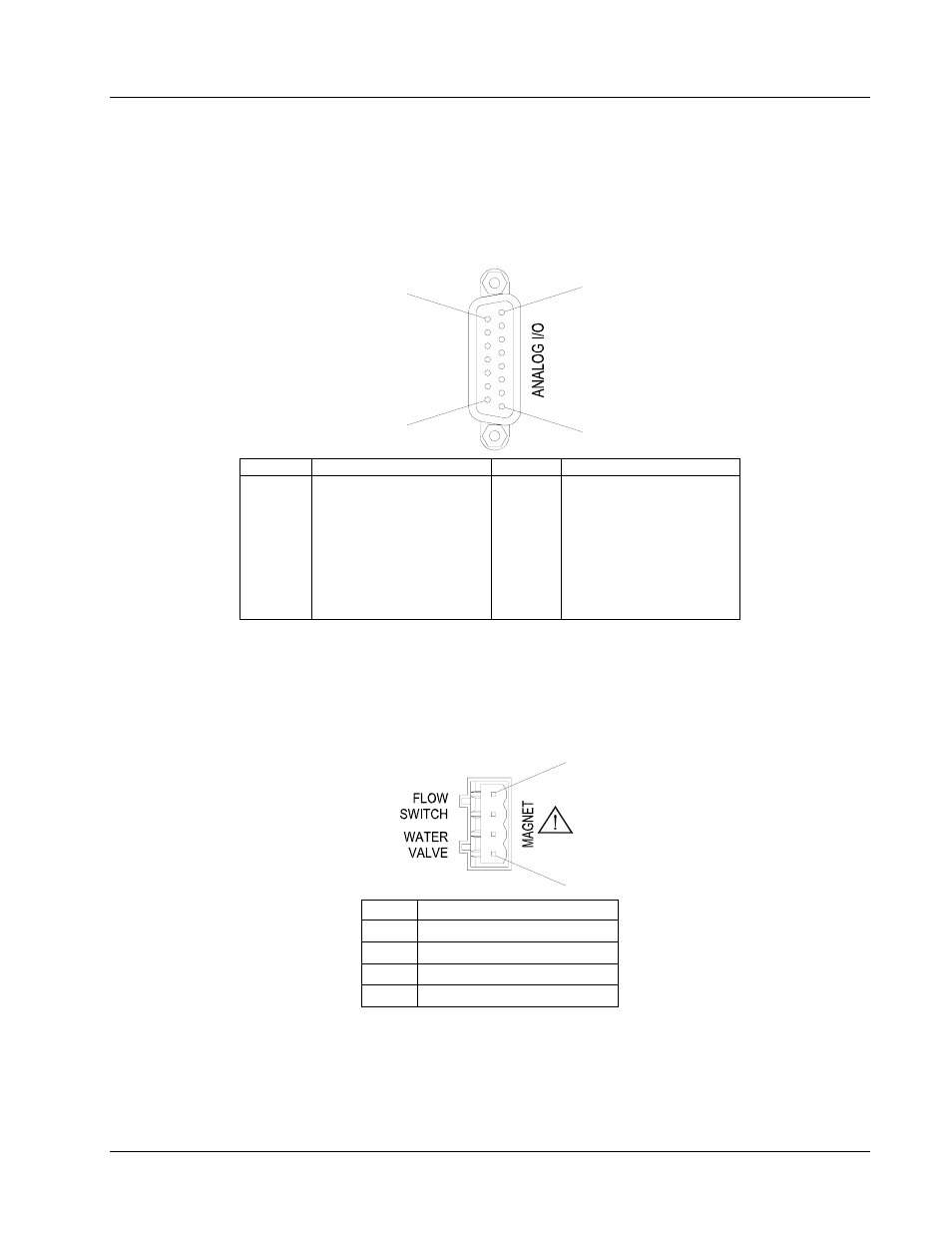
7.10.2 Magnet
Connector
The Magnet Water connector provides the means to connect a water control valve (24 VAC) and an associated water
flow switch (closed during flow) to protect the magnet from loss of water flow. Pins 1 & 2 must be closed for normal
operation. Pins 3 & 4 supply 24 VAC at 1 A for operation of a water control valve.
4
1
Pin Name
1 Flow
Switch
(Com)
2 Flow
Switch
3
Magnet Water Valve A
4
Magnet Water Valve B
Figure 7-8. Magnet Connector Details