Lakeshore Learning Materials 642 User Manual
Page 37
Lake Shore Model 642 Electromagnet Power Supply User’s Manual
Installation
3-9
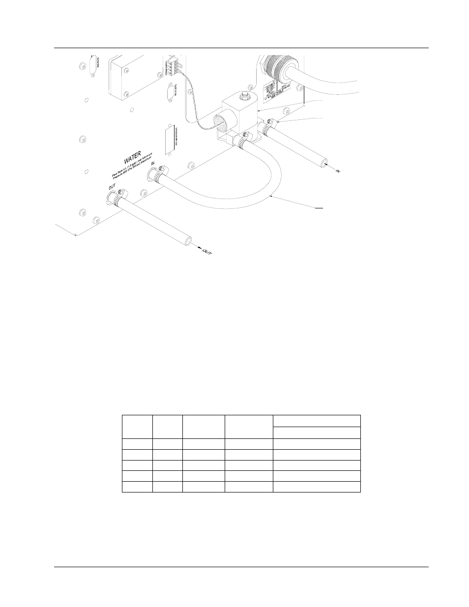
SOLENOID VALVE
WITH MOUNTING BRACKET
ADJUSTABLE HOSE CLAMP
REINFORCED HOSE
230 mm (9 in) LONG
Figure 3-12. Water Valve Connection
3.8
MAGNET CABLE CONNECTIONS
Magnet cable connections are made at the OUTPUT + and – terminals on the rear panel. These plated copper bus bars
accommodate M6 (¼ inch) mounting hardware. Two ¼-20 bolts, nuts, and Belleville washers are provided. Use load
wires heavy enough to limit the voltage drop to less than 0.5 volts per lead. This ensures proper regulation and keeps the
cables from overheating while carrying the required output current. Table 3-3 lists the current capacity and lead lengths
for load connections. Lake Shore sells magnet cables in 10 and 20 foot lengths. Refer to Paragraph 6.2 for ordering
accessories.
Figure 3-13 shows how the output cables are connected to the Model 642. A plain washer and a spring or Belleville
washer are provided. The Belleville washer is required to maintain contact pressure through varying material thickness
due to heating. The magnet leads should be dressed straight down to allow the installation of the protective lug cover.
Lug cover installation is shown in Figure 3-14.
Table 3-3. Current Capacity and Total Lead Lengths
Distance to Magnet
AWG
Area
(mm
2
)
Capacity
(A)
Resistivity
Ω
/1000 feet
Max Output of 70 A
0
53.5
245
0.09827
22 M (72 ft)
2
33.6
180
0.1563
14 M (45ft)
4
21.2
135
0.2485
8.5 M (28 ft)
6
13.3
100
0.3951
5.5 M (18 ft)
8
8.4
75
0.6282
3.4 M (11 ft)