Connecting wires to terminals – Kenwood DPX502 User Manual
Page 33
English
|
33
–
+
FRONT L
FRONT R
REAR L
REAR R
P.CONT
ILLUMI
ILLUMI
ANT.
CONT
MUTE
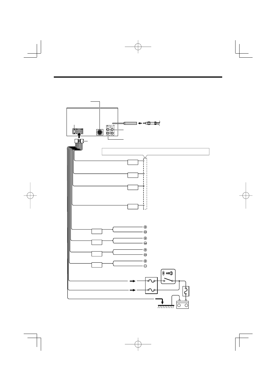
Connecting Wires to Terminals
Depending on what antenna you are using, connect
either to the control terminal of the motor antenna, or
to the power terminal for the booster amplifier of the
film-type antenna.
FM/AM
antenna input
Front left output (White)
Front right output (Red)
Fuse (10A)
To Kenwood disc changer/
External optional accessory
Wiring harness
(Accessory1)
White/Black
Gray/Black
Green/Black
Purple/Black
White
Gray
Green
Purple
To front left
speaker
To front right
speaker
To rear right
speaker
To rear left
speaker
Ignition wire (Red)
Battery wire (Yellow)
Ground wire (Black) - (To car chassis)
Ignition key
switch
Car fuse box
(Main fuse)
ACC
Car fuse box
Battery
If no connections are made, do not let the wire come out from the tab.
Rear left output (White)/ Sub Woofer left output (White)
Rear right output (Red)/ Sub Woofer right output (Red)
Motor antenna control wire (Blue)
Dimmer control wire (Orange / White)
To car light control switch
TEL mute wire (Brown)
Connect to the terminal that is grounded when either
the telephone rings or during conversation.
To connect the Kenwood navigation
system, consult your navigation manual.
⁄
⁄
Power control wire (Blue/White)
When using the optional power amplifier, connect
to its power control terminal.
To connect these leads, refer to the
relevant instruction manuals.