Installing options, Removing the top cover, Vgs-1 voice guide & storage unit – Kenwood TS-480SAT User Manual
Page 89: Yf-107c/ cn/ sn if filters and so-3 tcxo, 2 lift off the top cover, 4 insert the if filter(s) and/ or so-3 tcxo, Ext.sp data remote com mic panel, Vgs-1 connector
81
INSTALLING OPTIONS
You will require a #1 Philips screwdriver to install the
VGS-1. To install the YF-107 IF filter(s) and/ or SO-3
TCXO, you will also need a soldering iron (approx.
30 watts).
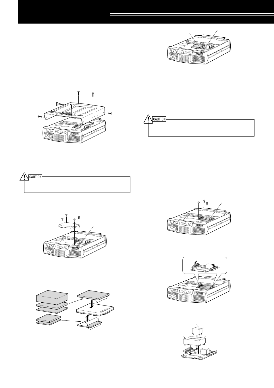
REMOVING THE TOP COVER
When installing the optional VGS-1, YF-107 IF filters
or SO-3 TCXO, remove the top cover of the
transceiver:
1 Remove the 8 screws.
PADDLE
KEY
EXT.SP
DATA
REMOTE
COM
MIC
PANEL
OPTION FIL
TER2
OPTION FIL
TER1
2 Lift off the top cover.
VGS-1 VOICE GUIDE & STORAGE UNIT
SWITCH OFF THE POWER AND UNPLUG THE DC POWER
CABLE BEFORE BEGINNING INSTALLATION.
1 Remove the top case (8 screws) {above}.
2 Loosen the 4 screws to remove the shield cover.
PADDLE
KEY
EXT.SP
DATA
REMOTE
COM
MIC
PANEL
TC
XO
OP
TIO
N
OPTION FIL
TER2
OPTION FIL
TER1
3 There are 5 rubber cushions in the VGS-1
package. Use the 2 rubber cushions shown below
and attach them to the VGS-1. The remaining
cushions are not used.
4 Plug the VGS-1 into the VGS-1 connector of the
PC board, pressing down on the top of the VGS-1
until secure.
PADDLE
KEY
EXT.SP
DATA
REMOTE
COM
MIC
PANEL
TC
XO
OPT
ION
OPTION FIL
TER2
OPTION FIL
TER1
5 Replace the shield cover and tighten the 4 screws.
6 Replace the top case (8 screws).
Note:
After the installation, you can adjust the VGS-1 playback
volume by selecting Menu Nos. 14 and 15.
YF-107C/ CN/ SN IF FILTERS AND SO-3 TCXO
SWITCH OFF THE POWER AND UNPLUG THE DC POWER
CABLE BEFORE BEGINNING INSTALLATION.
Three different types of IF filters (YF-107C,
YF-107CN, and YF-107SN) are available for the
TS-480 transceiver. You can install a maximum of 2
IF filters in the transceiver. Refer to page 90 for the
bandwidth information on each filter. As for the SO-3
option improves the transceiver frequency stability to
±0.5 ppm.
1 Remove the top case (8 screws).
2 Locate the filter and TCXO PCB and loosen the
3 screws.
PADDLE
KEY
EXT.SP
DATA
REMOTE
COM
MIC
PANEL
OPTION FIL
TER2
OPTION FIL
TER1
TC
XO
OP
TIO
N
3 Unlatch the connectors by pressing the connector
tabs upwards.
PADDLE
KEY
EXT.SP
DATA
REMOTE
COM
MIC
PANEL
OPTION FIL
TER2
OPTION FIL
TER1
OPTION FIL
TER2
OPTION FILTER1
TCXO
OPT
ION
TC
XO
OP
TIO
N
4 Insert the IF filter(s) and/ or SO-3 TCXO.
OPTION FIL
TER2
OPTION FIL
TER1
TCXO
OPT
ION
VGS-1 connector
VGS-1 connector
VGS-1
IF filter/ TCXO PCB
SO-3
Calibration hole
Secondary IF filter
Primary IF filter