Operating basics, Switching power on/ off, Adjusting volume – Kenwood TS-480SAT User Manual
Page 26: Selecting vfo a or vfo b, Af (audio frequency) gain, Rf (radio frequency) gain, A ” or, B ” appears to indicate which vfo is selected, Af sql
18
OPERATING BASICS
SWITCHING POWER ON/ OFF
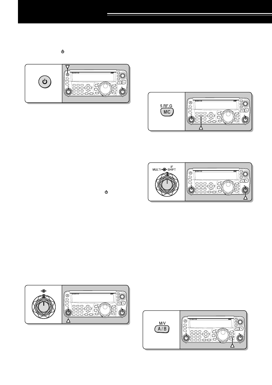
1 Switch the DC power supply(s) ON if you are
using a DC power supply(s).
2 Press and hold [ ] (POWER) briefly to switch
the transceiver ON.
NAR
1 REC
2 REC
5 RF.G
0 OFF
8
3 REC
9
4
7
TX MONI
6 DELAY
HF/50MHz ALL MODE TRANSCEIVER TS-480
CLR
STEP
SG.SEL
CW.T
F.LOCK
M/V
SPLIT
M VFO
M.IN
TF-SET
MULTI
IF
SHIFT
AF
SQL
PF
AT
CH1
CH2
CH3
PWR
MIC
KEY
VOX
PROC
AGC
ENT
A / B
A=B
MODE
MHz
QMI
QMR
MENU
MTR
NB/T
ANT 1/2
FINE
SCAN
DNL
BC
NR
FIL
RIT
XIT
CL
ATT/PRE
•
Do not press the switch for more than
approximately 2 seconds; the transceiver will
be switched OFF.
•
TS-480HX only: If “RX ONLY” appears on the
sub-display upon power up, confirm that two
DC cable connectors are securely connected to
the DC-1 and DC-2 connectors. When this
warning message appears, you can receive
signals as usual but you cannot transmit even if
you decrease the output power. “TWIN PWR”
appears when two DC power cables are
connected to the DC-1 and DC-2 connectors.
•
Upon power up, “HELLO” appears on the main
display, followed by the selected frequency and
other indicators.
3 To switch the transceiver OFF, press [ ]
(POWER) again.
4 Switch the DC power supply(s) OFF.
•
You may skip step 3. After switching the
transceiver ON, you can switch it OFF or ON
using only the power switch of the DC power
supply(s). The transceiver remembers the
information of the POWER switch position
when the DC power source is switched OFF.
ADJUSTING VOLUME
AF (AUDIO FREQUENCY) GAIN
Turn the AF control clockwise to increase the audio
level and counterclockwise to decrease the level.
NAR
1 REC
2 REC
5 RF.G
0 OFF
8
3 REC
9
4
7
TX MONI
6 DELAY
HF/50MHz ALL MODE TRANSCEIVER TS-480
CLR
STEP
SG.SEL
CW.T
F.LOCK
M/V
SPLIT
M VFO
M.IN
TF-SET
MULTI
IF
SHIFT
AF
SQL
PF
AT
CH1
CH2
CH3
PWR
MIC
KEY
VOX
PROC
AGC
ENT
A / B
A=B
MODE
MHz
QMI
QMR
MENU
MTR
NB/T
ANT 1/2
FINE
SCAN
DNL
BC
NR
FIL
RIT
XIT
CL
ATT/PRE
AF
SQL
Note:
The position of the AF control does not affect the volume of
beeps caused by pressing keys nor the CW TX sidetone. The audio
level for Digital mode operation is also independent of the AF control
setting.
RF (RADIO FREQUENCY) GAIN
The RF gain is normally configured to the maximum
level regardless of the operating modes. The
transceiver has been configured to the maximum
level at the factory. However, you may decrease the
RF gain slightly when you have trouble hearing the
desired signal because of excessive atmospheric
noise or interference from other stations. First, take
note of the peak S-meter reading of the desired
signal.
1 Press [MIC/ RF.G] (1 s).
NAR
1 REC
2 REC
5 RF.G
0 OFF
8
3 REC
9
4
7
TX MONI
6 DELAY
HF/50MHz ALL MODE TRANSCEIVER TS-480
CLR
STEP
SG.SEL
CW.T
F.LOCK
M/V
SPLIT
M VFO
M.IN
TF-SET
MULTI
IF
SHIFT
AF
SQL
PF
AT
CH1
CH2
CH3
PWR
MIC
KEY
VOX
PROC
AGC
ENT
A / B
A=B
MODE
MHz
QMI
QMR
MENU
MTR
NB/T
ANT 1/2
FINE
SCAN
DNL
BC
NR
FIL
RIT
XIT
CL
ATT/PRE
•
The current RF gain level appears on the
sub-display (0: minimum ~ 100: maximum).
2 Turn the MULTI control counterclockwise until the
S-meter reads the peak value that you noted.
NAR
1 REC
2 REC
5 RF.G
0 OFF
8
3 REC
9
4
7
TX MONI
6 DELAY
HF/50MHz ALL MODE TRANSCEIVER TS-480
CLR
STEP
SG.SEL
CW.T
F.LOCK
M/V
SPLIT
M VFO
M.IN
TF-SET
MULTI
IF
SHIFT
AF
SQL
PF
AT
CH1
CH2
CH3
PWR
MIC
KEY
VOX
PROC
AGC
ENT
A / B
A=B
MODE
MHz
QMI
QMR
MENU
MTR
NB/T
ANT 1/2
FINE
SCAN
DNL
BC
NR
FIL
RIT
XIT
CL
ATT/PRE
•
Signals that are weaker than this level will be
attenuated and reception of the station will
become easier.
Depending on the type and gain of your antenna, and
the condition of the band, adjust the RF gain. When
using FM mode, always adjust the RF gain to the
maximum level.
SELECTING VFO A OR VFO B
Two VFOs are available for controlling the frequency
on the transceiver. Each VFO (VFO A and VFO B)
works independently so that a different frequency and
mode can be selected. For example, when SPLIT
operation is activated, VFO A is used for reception
and VFO B is used for transmission. The opposite
combination is also possible.
Press [A/B / M/V] to toggle between VFO A and B.
NAR
1 REC
2 REC
5 RF.G
0 OFF
8
3 REC
9
4
7
TX MONI
6 DELAY
HF/50MHz ALL MODE TRANSCEIVER TS-480
CLR
STEP
SG.SEL
CW.T
F.LOCK
M/V
SPLIT
M VFO
M.IN
TF-SET
MULTI
IF
SHIFT
AF
SQL
PF
AT
CH1
CH2
CH3
PWR
MIC
KEY
VOX
PROC
AGC
ENT
A / B
A=B
MODE
MHz
QMI
QMR
MENU
MTR
NB/T
ANT 1/2
FINE
SCAN
DNL
BC
NR
FIL
RIT
XIT
CL
ATT/PRE
•
“
t
A” or “
t
B” appears to indicate which VFO is
selected.