4 - wiring the switchplate, 4 wiring the switchplate, Tips for safe and successful wiring – KVH Industries TracVision 4 User Manual
Page 26
2.4
Wiring the Switchplate
All other wiring for the TracVision system connects to the
switchplate. For the TracVision system to work, you must wire
the following cables to the switchplate:
•
Antenna Data Cable
•
Antenna Power Cable
•
Vessel Power Cable
•
IRD Ground Cable(s)
Tips for Safe and Successful Wiring
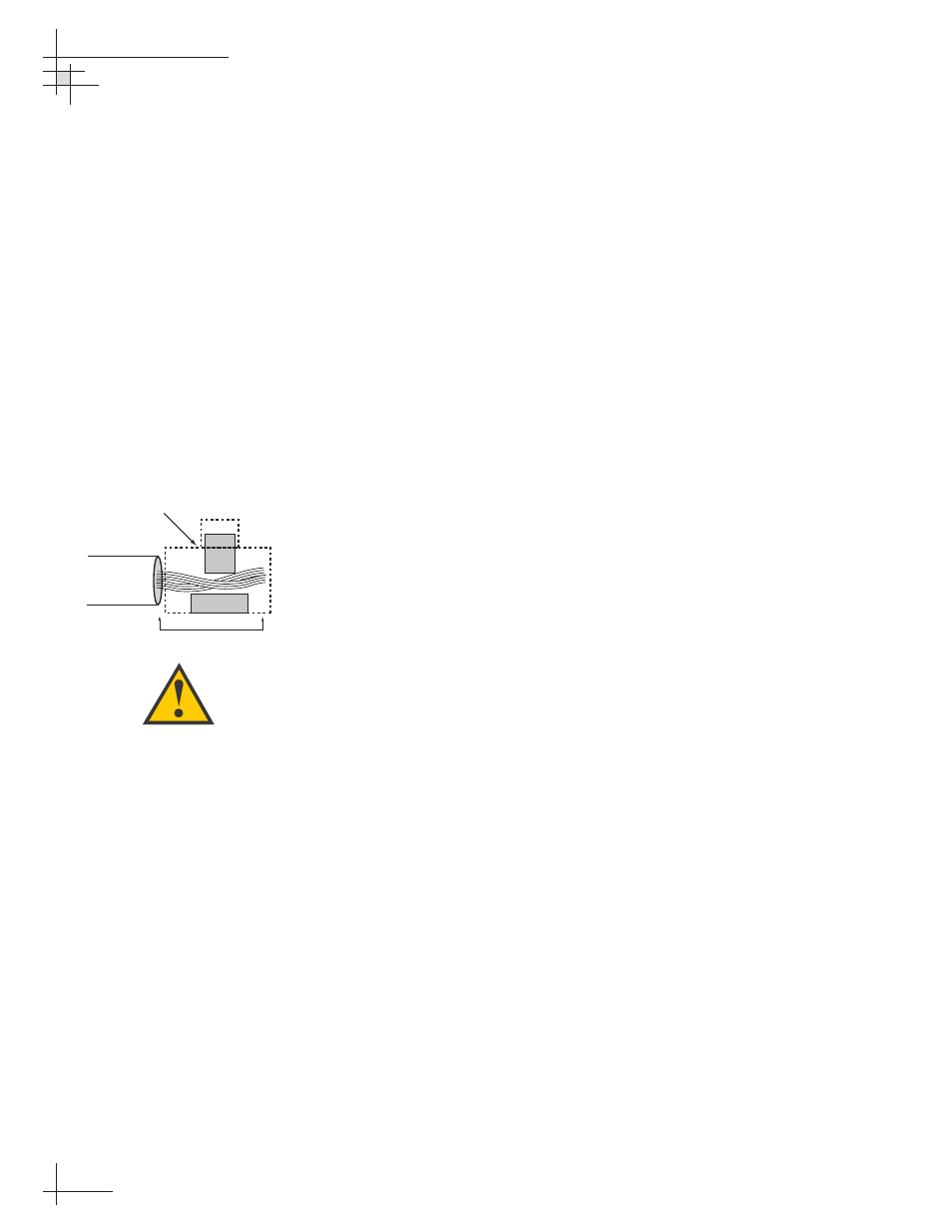
•
When attaching cables to the TracVision 4
switchplate connectors, make sure the insulation is
stripped back approximately
1
⁄
4
" (6 mm). Twist the
wires gently to help achieve a good connection. Do
not pinch insulation inside the connector.
•
After attaching the power and data cables to the
appropriate terminal connector strips, tug gently
to ensure a firm connection.
•
Do not tin (solder) the wire ends.
•
All cables should be routed and dressed before
terminating at the switchplate. The antenna data
and power cables may be trimmed to desired
length. However, be sure to cut back the data
cable’s drain wire (shield); do NOT connect the
drain wire to anything.
54-0150
22
TracVision 4 Technical Manual
Insulation
Terminal Connector
1/4" (6 mm)
Figure 2-12
Correctly Securing Wires within
the Switchplate Connectors
Do NOT connect the antenna data
cable’s drain wire (shield).