2 - mounting the tracvision antenna, 2 mounting the tracvision antenna, Figure 2-4 antenna mounting holes layout – KVH Industries TracVision 4 User Manual
Page 19
2.2
Mounting the TracVision
Antenna
1. Make sure that you have chosen a suitable
mounting location based upon the guidelines in
“Choosing the Best Location for the TracVision
Antenna” on page 12.
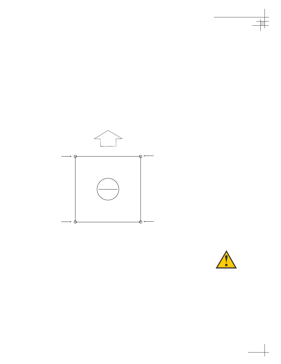
2. Using the template provided in Appendix B on
page 73 or the dimensions shown in Figure 2-4, lay
out the four mounting bolt holes and cable access
hole at the mounting site. Make certain that the
“FWD” arrow is parallel with the vessel’s
centerline and pointed toward the bow.
3. Drill the four
3
⁄
8
" (10 mm) bolt holes and cut out the
3" (80 mm) diameter cable access hole (following
the layout in Step 2). Smooth the edges of the cable
access hole to protect the cables.
4. Bring the data cable, power cable, and RF cable(s)
from belowdecks up through the cable access hole
in the mounting surface (see Table 2-1 on page 9 to
determine the number of RF cables required).
Belowdecks, route the opposite end(s) of the RF
cable(s) to the IRD(s) or multiswitch; route the
opposite ends of the data cable and power cable
through the switchplate panel cutout.
5. Remove the antenna unit from its shipping carton.
Installation
54-0150
15
Drill 3/8" (10 mm)
Bolt Hole
9" (229 mm)
3" (80 mm)
Drill 3/8" (10 mm)
Bolt Hole
Drill 3/8" (10 mm)
Bolt Hole
Drill 3/8" (10 mm)
Bolt Hole
C
u
t
ou
t fo
r Cable A
cc
es
s
9" (229 mm)
9" (229 mm)
9" (229 mm)
FWD
Figure 2-4
Antenna Mounting Holes Layout
Always lift the antenna unit by the
gray baseplate and never by the
radome or any portion of the
antenna assembly. Also be careful
not to strike the exposed
connectors extending from the
bottom of the baseplate or allow
them to carry the weight of the
antenna unit.