Kenwood KDV-412 User Manual
Page 77
English 77
Installa
tion
• Never insert the screws in any other screw hole than the
one specified. If you screw them in another hole, it will
contact and may cause damage to the mechanical parts
inside the unit.
Removing the hard rubber frame
1
Engage the catch pins on the removal tool and
remove the two locks on the upper level.
Upper the frame and pull it forward as shown
in the figure.
Catch
Lock
Accessory
2
Removal tool
2
When the upper level is removed, remove the
lower two locations.
• The frame can be removed from the bottom side in the
same manner.
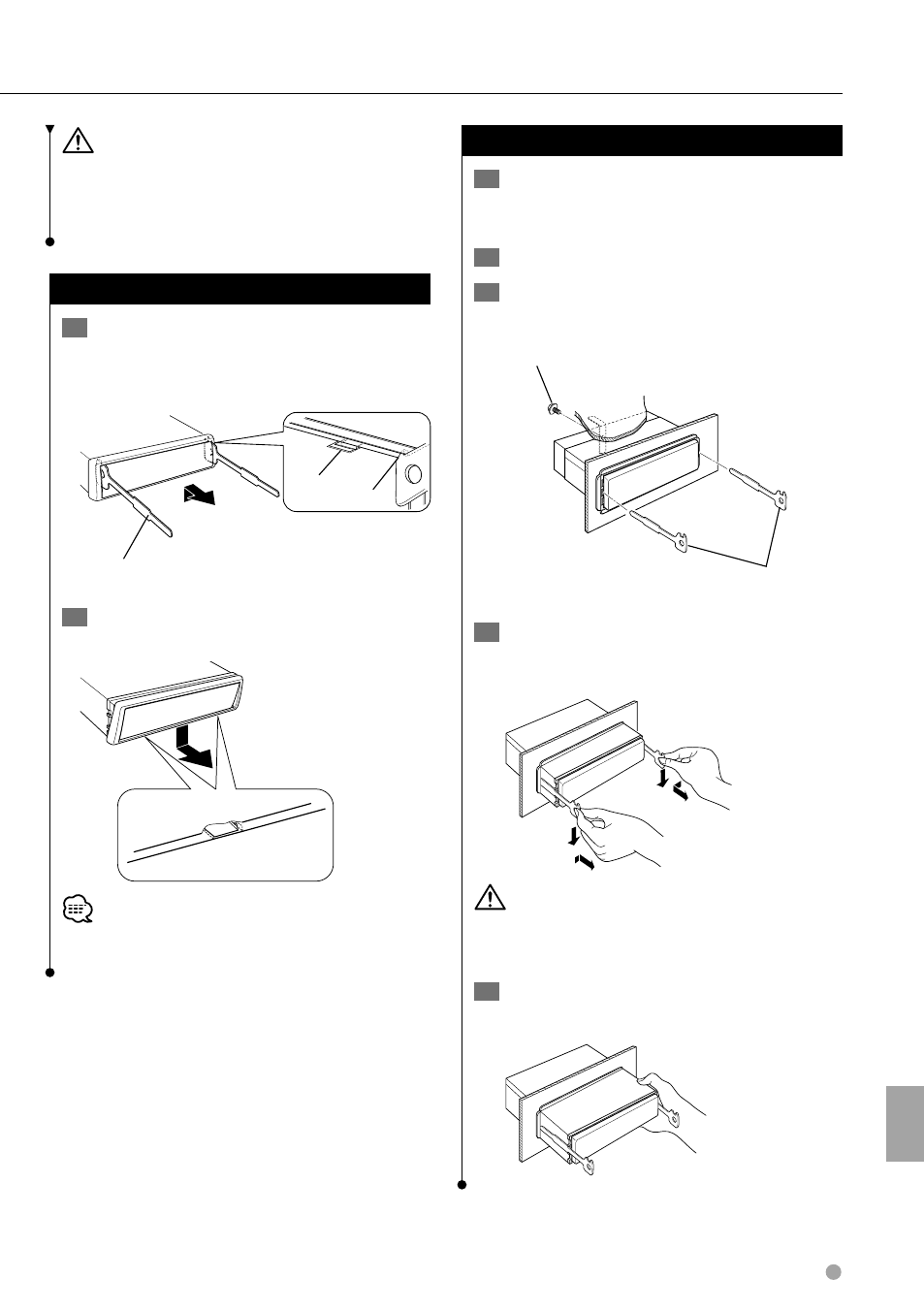
Removing the Unit
1
Refer to the section rubber frame> (page 77) and then remove the 2 Remove the screw (M4 × 8) on the back panel. 3 Insert the two removal tools deeply into the slots on each side, as shown. Accessory 2 Removal tool Screw (M4×8) 4 Lower the removal tool toward the bottom, and pull out the unit halfway while pressing • Be careful to avoid injury from the catch pins on the removal tool. 5 Pull the unit all the way out with your hands, being careful not to drop it.
hard rubber frame.
(commercially available)
towards the inside.