Power supply circuit, Optional board terminal, Circuit description – Kenwood TK-480 User Manual
Page 20
19
TK-480/481
CIRCUIT DESCRIPTION
7-2. Decode
• Low-speed data (QT,DQT,LTR)
The demodulated signal from the IF IC (IC9) is amplified
by IC8 (1/2) and passes through a low-pass filter (IC10) to
remove audio components. The signal is input to pin 23 of
the CPU.
The CPU digitizes this signal, performs processing such
as DC restoration, and decodes the signal.
• High-speed data (DTMF)
The DTMF input signal from the IF IC is amplified by IC8
(1/2) and goes to IC13, the DTMF decoder. The decoded in-
formation is then processed by the CPU. During transmis-
sion and standby, the DTMF IC is set to the power down
mode when the PD terminal is High. When the line is busy,
the PD terminal becomes Low, the power down mode is
canceled and decoding is carried out.
• MSK
The MSK input signal from the IF IC is amplified by IC8 (1/
2) and goes to pin 5 of IC12. The signal is demodulated by
MSK demodulator in IC12. The demodulated data goes to
the CPU for processing.
Fig. 13
Decode
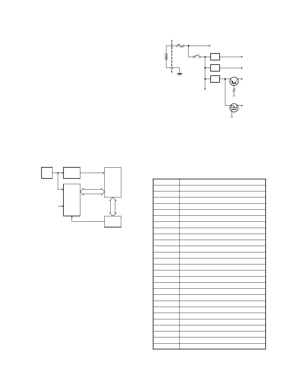
8. Power Supply Circuit
Battery +B is supplied via a 3A fuse from the battery ter-
minal connected to the TX-RX unit. After passing through
the power switch, power supply (SB) is applied to the three
AVRs. IC5 supplies 5V (5M) to the control circuit, and IC7
supplies 5V (5C) to common circuits. IC6 supplies to the TX
circuit and the RX circuit. During transmission, 5TC be-
comes Low and Q2 is turned ON to supply 5V (5T) to the TX
circuit. During reception, 5RC becomes Low and Q1 is
turned ON to supply 5V (5R) to the RX circuit.
Fig. 14
Power supply circuit
9. Optional Board Terminal
Terminals for mounting the option board are provided at
the bottom edge of the TX-RX unit. The table below shows
the correspondence between the board and terminals.
R422, R32, R250, R259, R147, R276, R421 may have to be
removed depending on the type of option board being used.
Name
Function
SB
Battery (7.5V)
GND
Ground
TXD
Serial data
RXD
Serial data
SQ
Busy: high
LOK
Link acquired : low (TX mode)
DI/ANI
Modulation (ANI) input
DEO
Detect output
TXAI/MUTE
Modulation output from board or mic mute: low
TXAO
Modulation input to board
RXAI
Received signal input to board
RXAO
Received signal output from board
D1
Binary 1
D2
Binary 2
OPT
Scramble, Emergency: low
PTTIN
PTT switch signal input to board (TX: low)
5CNS
Battery (5V)
DI9
9600 bps data output
RXEMAO
Received signal output from board (after de-emphasis)
RXEMAI
Received signal input to board (after de-emphasis)
PTTOUT
PTT switch signal output from board (TX: low)
MONI
Busy: low
LAMP
Busy: low
AAC
Audio Amp Control signal output from board (Busy: high)
Audio Beep
Beep signal output from board
AUX TXD
Serial data
AUX RXD/EXTSW
Serial data/Option switch port
Table 1
Terminal name and function
IC10
LPF
IC13
DTMF
DECODE
IC12
XOUT
OSC1
PD
DCK,SD,STD
DT
,CK,CE
7
IC19
23 LSD
IN
IC15
CPU
IC8
AMP
IC5
SB
IC7
IC6
5TC
Q2
5T
5RC
5R
5M
5C
+B
F1
ON/OFF
VOL
RF power amp (IC30)
Display unit
Q1