Circuit description, Overview, Circuit configuration by frequency – Kenwood TK-480 User Manual
Page 15: Receiver system, Fig. 1 frequency configuration, 1. rf unit, 2. if unit, Fig. 2 receiving system
14
TK-480/481
1. Overview
This transceiver is an 800/900MHz band EFJ LTR™
trunked system compatible FM portable transceiver that can
be programmed to operate on both LTR and conventional
systems.
2. Circuit Configuration by Frequency
The receiver is a double-conversion superheterodyne
with a first intermediate frequency (IF) of 44.85MHz and a
second IF of 455kHz. Incoming signals from the antenna are
mixed with the local signal from the PLL to produce the first
IF of 44.85MHz.
This is then mixed with the 44.395MHz second local os-
cillator output to produce the 455kHz second IF. This is de-
tected to give the demodulated signal.
The transmit signal frequency is generated by the PLL
VCO, and modulated by the signal from the microphone. It
is then amplified and sent to the antenna.
Fig. 1
Frequency configuration
ANT
ANT
SW
RF
AMP
1st MIX
MCF
CF
455kHz
IF SYSTEM
TK-480
TX 806~825MHz
851~870MHz
RX 851~870MHz
TK-481
TX 896~902MHz
935~941MHz
RX 935~941MHz
AF
AMP
44.395
MHz
PA
AMP
TX
AMP
MIC
AMP
44.85MHz
TK-480 :
806.15~825.15MHz
TK-481 :
890.15~896.15MHz
TK-480
806~825MHz
851~870MHz
TK-481
896~902MHz
935~941MHz
PLL
VCO
SP
MIC
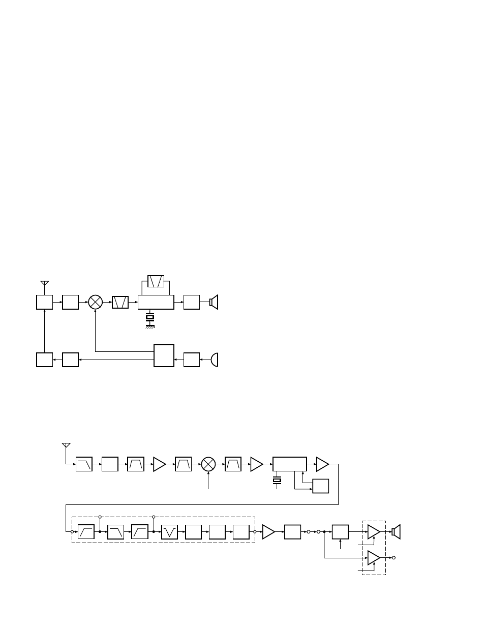
3. Receiver System
3-1. RF unit
An incoming RF signal from the antenna terminal is
passed through the antenna switch (D7, D9, and D10 are
off) and then the bandpass filter (L11). The signal is ampli-
fied by RF amplifier Q9, and passed through the bandpass
filter (L20) to remove the spurious signal again. The result-
ing signal is applied to the first mixer (Q6), where it is mixed
with the first local oscillator signal output from the fre-
quency synthesizer to produce the first IF (44.85MHz).
3-2. IF unit
The first IF signal is passed through a four-pole mono-
lithic crystal filter (XF1) to remove a adjacent channel signal.
The filtered first IF signal is amplified by the first IF amplifier
(Q5) and then applied to the IF system IC (IC9). The IF sys-
tem IC provides a second mixer, second local oscillator, lim-
iting amplifier, quadrature detector and RSSI (Received Sig-
nal Strength Indicator). The second mixer mixes the first IF
signal with the 44.395MHz of second local oscillator output
(crystal unit X1) and produces the second IF signal of
455kHz.
The second IF signal is passed through the ceramic filter
(CF1,2) to more remove the adjacent channel signal. The
filtered second IF signal is amplified by the limiting amplifier
and demodulated by the quadrature detector with ceramic
discriminator (CD1). The demodulated signal is routed to
the audio circuit.
Fig. 2
Receiving system
ANT
SW
CF1
CF2
1st local
OSC (PLL)
2nd local
OSC
X1
L30
D9,D10
L11
BPF
Q9
RF AMP
L20
BPF
Q6
1st MIX
XF1
MCF
Q5
1st IF
IC9
MIX,DET,IF
IC8 (2/2)
AF AMP
41
IC3 (2/2)
AF AMP
IC4
VOL
AF AF
Q310
SW
SSW
VC1
VC2
IC300
AF PA
INT.
SP
EXT.
SP
HPF
DE-
EMP
LPF
HPF
BEF
5
2
1
IC12
ANT
EXP
MUTE
CIRCUIT DESCRIPTION