Transmitter system, Circuit description – Kenwood TK-480 User Manual
Page 16
15
TK-480/481
CIRCUIT DESCRIPTION
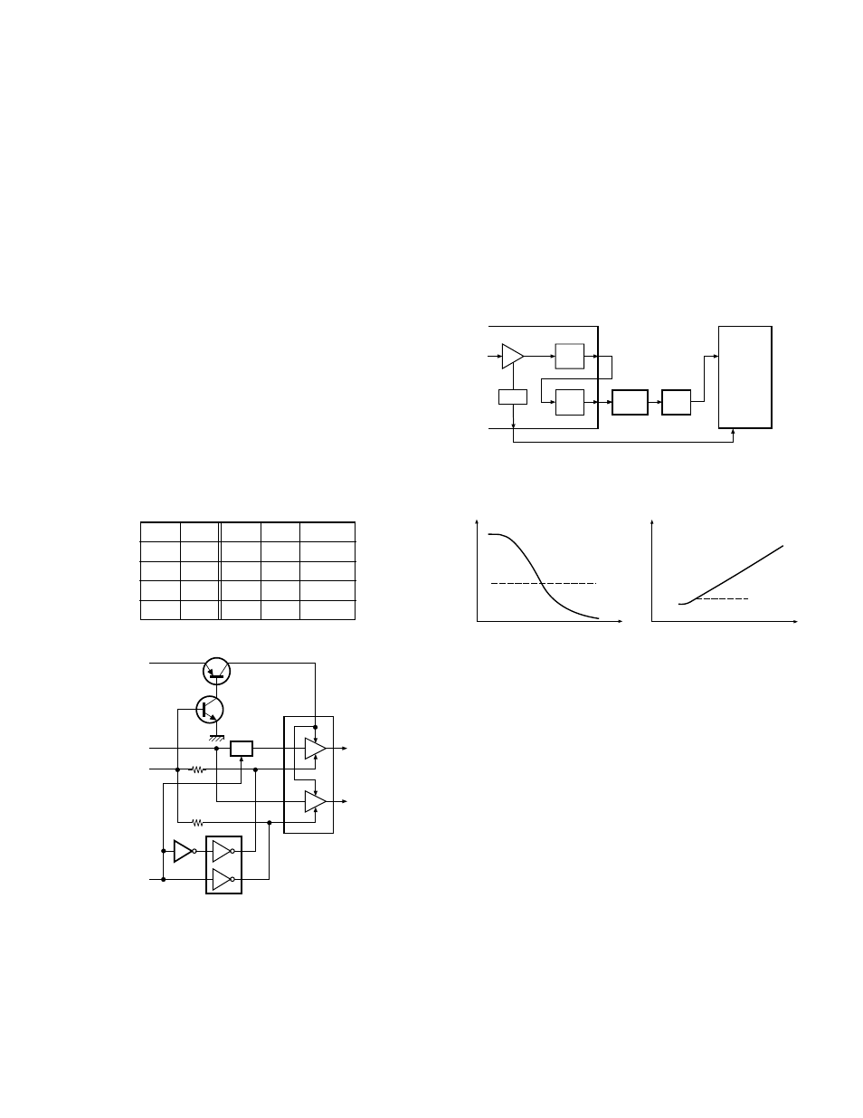
3-3. Audio amplifier circuit
The demodulated signal from IC9 is amplified by IC8 (2/
2), high-pass filtered, low-pass filtered, high-pass filtered,
band-eliminate filtered,and de-emphasized by IC12.
The signal then goes through an AF amplifier IC3 (2/2), an
electronic volume control (IC4), and an AF switch (Q310 is
on), and is routed to audio power amplifier (IC300), where it
is amplified and output to the internal speaker.
The audio mute signal (AM) from the microcomputer be-
comes Low in the standby and Q304, Q305 which are
power supply circuit for IC300 turn off. Also, IC12 is set to
the power down mode according to data from microproces-
sor, and the AF signal is muted. When the audio is output,
AM becomes High to turn Q304, Q305 ON, and voltage is
supplied to power terminal VP of IC300. Also, IC12 is can-
celed out of the power down mode.
The speaker is switched by the logic of speaker switch-
ing terminal SSW on the universal connector. When SP-MIC
is not attached, the logic of SSW becomes High and SW
(Q310) is turned ON, and the AF signal is input to both ampli-
fiers of IC300.
When SP-MIC is attached, SSW is connected to GND at
inside of SP-MIC. For this reason, Q310 is turned OFF, and
the AF signal is input only to amplifier for EXT SP of IC300.
Change of INT/EXT SP refer to Fig. 3.
AM
SSW
VC1
VC2
SP
H
H
H
L
INT
H
L
L
H
EXT
L
H
L
L
MUTE
L
L
L
L
MUTE
Fig. 3
Audio amplifier circuit
SW
2
VC1
8
VC2
5
VP
Q305
Q304
IC300
INT. SP
EXT. SP
Q301
Q308
AF
AM
SSW
SB
3-4. Squelch circuit
The output from IC9 enters FM IC again, then passed
through a band-pass filter. The noise component output
from IC9 is amplified by Q19 and rectified by D3 to produce
a DC voltage corresponding to the noise level. The DC volt-
age is sent to the analog port of the CPU (IC15). And IC9
outputs a DC voltage (RSSI) corresponding to the input of
the IF amplifier. The CPU reads the RSSI signal via pin 24.
IC15 determines whether to output sounds from the
speaker by comparing the input voltage of pin 28 and pin 24
with the preset value.
Fig. 4
Squelch circuit
Fig. 5
Squelch and RSSI voltage vs ANT input level
IF AMP
DET
RSSI
BPF
AMP
NOISE
AMP
DET
Q19
D3
28
IC15
CPU
24
IC9 : FM IF IC
7
12
SQ voltage
ANT input level
SQ close
SQ open
RSSI voltage
ANT input level
Preset
value
Preset
value
4. Transmitter System
4-1. Microphone amplifier
The signal from the internal microphone goes through
the mute switch (Q300).
When the SP-MIC is not attached, the microphone
switching terminal (MSW) on the universal connector be-
comes High, and mute switch (Q300) is turned ON. When
the SP-MIC is attached, MSW is connected to GND at inside
of SP-MIC. For this reason, Q300 is turned OFF, the internal
microphone is muted, and only the input of the external mi-
crophone is supplied to the microphone amplifier of the TX-
RX unit.