Signalling circuit, Circuit description, 2. low battery warning – Kenwood TK-480 User Manual
Page 19: 3. key input, 1. encode • low-speed data (qt,dqt,ltr), High-speed data (dtmf), Fig. 12 encode
18
TK-480/481
CIRCUIT DESCRIPTION
6-2. Low battery warning
The battery voltage is monitored by the microprocessor
(IC15). When the battery voltage falls below the voltage set
by the Low Battery Warning adjustment, the red LED
flashes to notify the operator that it is time to replace the
battery. If the battery voltage falls even more (approx. 5.8V),
a beep sounds and transmission is stopped.
Low battery warning
Battery condition
The red LED flashes during
The battery voltage is low but
transmission
the transceiver is still usable.
The red LED flashes and
The battery voltage is low and
continuous beep sounds
the transceiver is not usable to
while PTT pressed
make calls.
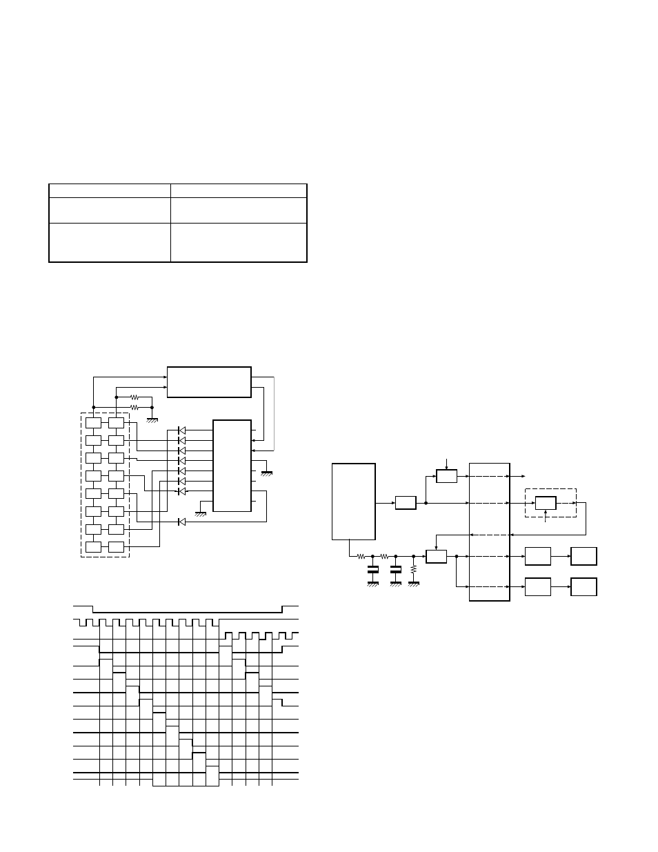
6-3. Key input
If the clock is supplied to CLK terminal when the RES
terminal (CPU pin 53) of the decade counter (IC301) is set to
Low, Q0 to Q7 become High sequentially. Normally, KI1 and
KI2 are Low (pulled down). When any key is pressed, KI1 or
KI2 become High. The CPU detects which key is pressed,
according to the voltage of KI1 and KI2 and clock timing.
Fig. 10
Key input
Fig. 11
Decade counter timing chart
7. Signalling Circuit
7-1. Encode
• Low-speed data (QT,DQT,LTR)
Low-speed data is output from pin 36 of the CPU. The
signal passes through a low-pass CR filter, and goes to the
summing amplifier (IC3 1/2). The signal is mixed with the
audio signal and goes to the VCO (IC14) and VCXO (X2)
modulation input after passing through the D/A converter
(IC4) for BAL adjustment.
• High-speed data (DTMF)
High-speed data is output from pin 35 of the CPU. The
signal passes through a low-pass filter consisting of IC23,
and provides a TX DTMF tone and a RX DTMF tone including
a beep tone. The TX DTMF tone is passed to the D/A con-
vertor (IC4) for DTMF deviation adjustment, and then ap-
plied to the audio processor (IC12).
The signal is mixed with the audio signal and goes to the
VCO and VCXO. The RX DTMF tone is passed a summing
amplifier (IC3 2/2), the D/A convertor (IC4) for audio control,
audio power amplifier and then to the speaker.
• MSK
MSK signal is output from pin 6 of IC12. The signal
passes through the D/A converter (IC4) for the MSK devia-
tion adjustment, and is routed to the VCO. When encoding
MSK, the microphone input signal is muted.
Fig. 12
Encode
KI2
Q5
Q1
Q0
Q2
Q6
Q7
Q3
Vss
Vdd
RES
CLK
CL
CA
Q9
Q4
Q8
KRST
CK
IC301
KI1
IC15
CPU
16 keys
RESET
CLOCK
Q0
Q1
Q2
Q3
Q4
Q5
Q6
Q7
Q8
Q9
CLOCK
INHIBIT
CARRY
OUT
BUFF
AMP
VCXO
MB
X2
IC1
AF
MUTE
VCO
MD
IC14
Q21
LPF
35
HSD
OUT
IC23
R111
R107
C141
C138
R148
LSD
OUT
IC15
CPU
I3
I2
IC4
D/A (ADJ)
SUM
MIC IN
SUM
IC3 (1/2)
O2
I1
O1
IC12
AF AMP
SUM
O5
I5
O3
36
O6
I6
IC3 (2/2)
RX audio