Appendix, Return video signal input and output, Alarms (when the xdca-55 is used) – Sony XDCU-50 User Manual
Page 21
21
Appendix
Appendix
Return Video Signal Input and Output
Return video signals input to this unit are sent to the
camera adaptor as HDSDI signals. The camera adaptor
switches between the return video signal received from
this unit and the signal received from the camcorder, and
outputs the signal from the MONI.OUT connector. The
XDCA-55 sends return video received from this unit to the
camcorder via its camcorder connection connector
(50-pin).
As return video signals, this unit accepts HDSDI signals,
SDSDI signals, and SD analog composite signals. HDSDI
and SDSDI return video signals are input from the unit’s
RETURN INPUT SDI connector. SD analog composite
return video signals are input from the unit’s RETURN
INPUT VIDEO connector. Use the HDSDI/SDSDI/
VIDEO switch (one of the RETURN INPUT SELECT
switches) to select which of these signals to use as the
return video signal (see page 13).
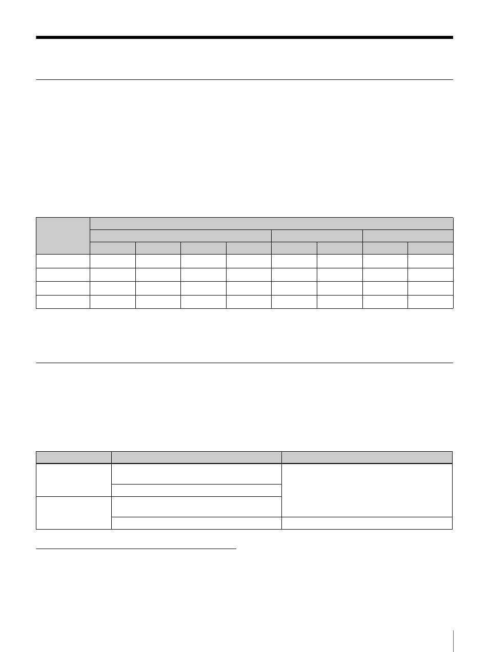
The format of the return video signals that can be input to
this unit varies as shown in the following table, according
to the system format settings of this unit and the
camcorder.
a
: Yes –: No
When a return video signal is input to this system, and that
signal in not synchronized with this system, you can
synchronize it by using the internal frame synchronizer of
this unit.
Switching the Monitor Output of the XDCA-55/XDCA-53
The monitor output from the MONITOR OUT (SDI)
connector of the XDCA-55 or MONITOR OUT connector
and MONI.OUT (SDI) connector of the XDCA-53 can be
switched between return video signals sent from this unit
and the shooting or playback signals sent from the
camcorder.
The monitor output from the XDCA-55/53 is switched as
shown in the following table, according to the settings of
the MONI. SEL switch and the RET button on the camera
adaptor.
Alarms (when the XDCA-55 is used)
The TALLY lamp (red) flashes as an alarm if the system
frequencies of this unit and the camcorder are different.
Even if the TALLY lamp is already lit, it changes to
flashing if an alarm occurs.
For details about the system frequency of this unit and that
of the camcorder, see “Setting the System Format”
(page 19).
System
format
Formats of return video signals that can be input to this unit
HDSDI
SDSDI
SD analog composite
1080/59.94i 720/59.94P
1080/50i
720/50P
486/59.94i
576/50i
525/59.94i
625/50i
1080/59.94i
a
–
–
–
a
–
a
–
720/59.94P
–
a
–
–
a
–
a
–
1080/50i
–
–
a
–
–
a
–
a
720/50P
–
–
–
a
–
a
–
a
MONI. SEL switch
RET button state
Monitor output
RET
On (the RET button is pressed on one of the
devices in the system)
Return video signal
Off (the RET button is not pressed)
CAM/RET
On (the RET button is pressed on one of the
devices in the system)
Off (the RET button is not pressed)
Shooting or playback signals sent from the camera