Connecting the cables, 7overview, Lights in green when power is input – Sony Ericsson XCI-V3 User Manual
Page 7: Lights in red when the bios is starting up, Push to restart the camera
7
Overview
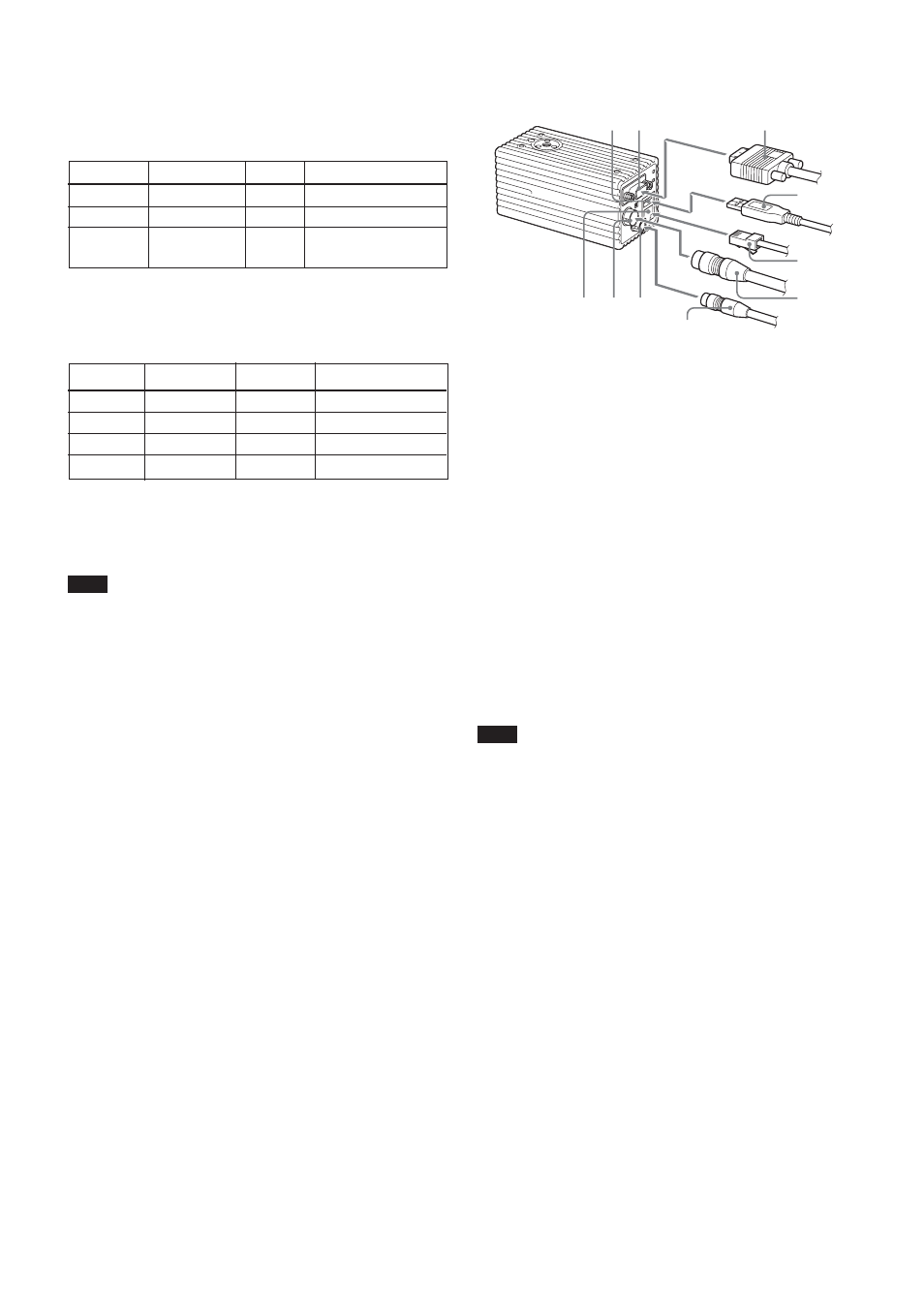
Connecting the cables
1
Monitor cable
6
MONITOR connector
2
USB cable
7
USB connector
3
LAN cable
8
DC IN connector
4
Camera cable
9
SERIAL connector
5
Serial cable
0
LAN connector
Connect the camera cable to the DC IN connector.
Also, if needed, connect the LAN cable to the LAN
connector, the monitor cable to the MONITOR
connector, the serial cable to the SERIAL connector,
and the USB mouse/keyboard to the USB connector
respectively.
When you connect the monitor cable, turn the two
fastening screws to secure the cable tightly.
Connect the other end of the camera cable to the DC-
700/700CE. Also, if needed, connect the LAN cable to
the host device, and the monitor cable to the monitor,
and the serial cable to the camera control device.
Note
Make sure to supply power to the camera module and
confirm that the camera module is operating before
inputting a trigger signal. If you input external signals
to a camera module without the power supplied, this
may cause a malfunction of the camera module.
7
6
1
q;
8
9
5
4
3
2
9
SERIAL connector (6-pin)
You can connect a serial cable to this connector to
control a camera from a camera control device (e.g.,
PC).
Pin No.
Signal
Pin No.
Signal
1
TXD
4
ISO input +
2
RXD
5
ISO input –
3
Ground
6
XCI-SX1: NC
XCI-V3: TTL output 2
q;
LAN connector
You can connect a LAN cable to this connector to
output a video signal to the host device.
Pin No.
Signal
Pin No.
Signal
1
TD+
5
NC
2
TD–
6
RD–
3
RD+
7
NC
4
NC
8
NC
qa
MODE switches
For service use. Both switches are set to the left side as
the factory setting.
Note
If either of these switches is set to the right side, the
camera doesn’t start normally.
qs
POWER LED
Lights in green when power is input.
qd
STATUS LED
Lights in red when the BIOS is starting up.
qf
RESET switch
Push to restart the camera.