Drive/head register, Table 23: drive/head register – Silicon Image SiliconDrive SSDS00-3650H-R User Manual
Page 33
ATA R
EGISTERS
SSD-H
XXX
(I)-3650 D
ATA
S
HEET
S
ILICON
S
YSTEMS
P
ROPRIETARY
This document and the information contained within it is confidential and proprietary to SiliconSystems, Inc.
All unauthorized use and/or reproduction is prohibited.
D
OCUMENT
: 3650H-02DSR
J
UNE
17, 2008
P
AGE
21
D
RIVE
/H
EAD
R
EGISTER
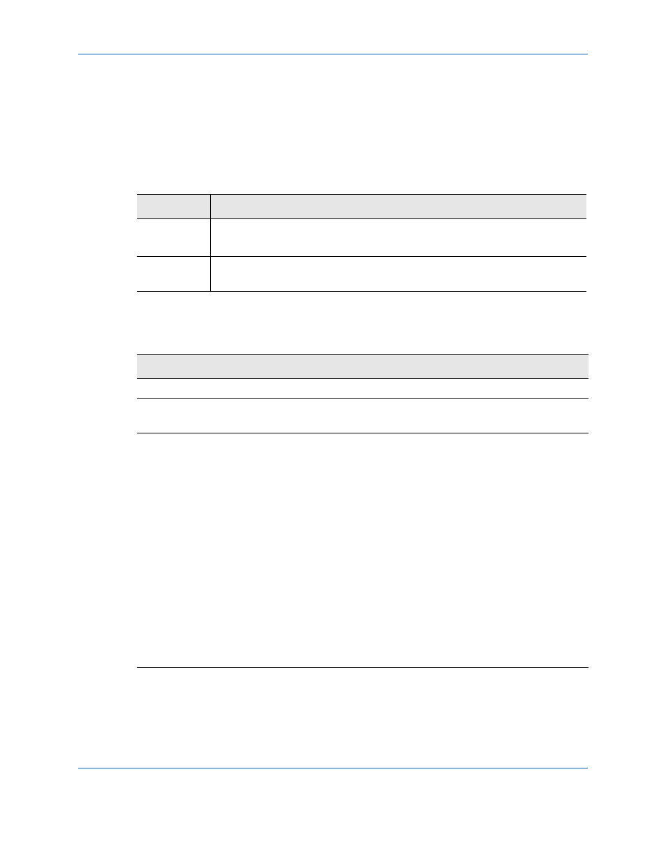
The Drive/Head register is used by the host and the device to select the type
of addressing (CHS or LBA), the drive letter, and either bits 3-0 of the head
number in CHS mode or logical block number bits 27-24 in LBA mode.
The Drive/Head register is used by the host to specify one of a pair of ATA
drives present in the platform.
Table 23: Drive/Head Register
Operation
D
7
D
6
D
5
D
4
D
3
D
2
D
1
D
0
Read/Write
1
LBA
1
DRV
HS3
LBA27
HS2
LBA26
HS1
LBA25
HS0
LBA24
Default
Value
1
0
1
0
0
0
0
0
Bit(s)
Description
6
LBA.
Selects between CHS (0) and LBA (1) addressing mode.
4
Drive Address (DRV).
Indicates the drive number selected by the
host, either 0 or 1.
3-0
HS3 to 0. Indicates bits 3-0 of the head number in CHS addressing
mode or LBA bits 27-24 in LBA mode.
• CHS to LBA conversion: LBA = (C x HpC + H) x SpH + S -1
• LBA to CHS conversion:
C = LBA/(HpC x SpH)
H = (LBA/SpH) mod (HpC)
S = (LBA mod(SpH)) + 1
...where:
C is the cylinder number
H is the head number
S is the sector count
HpC is the head count per cylinder count
SpH is the sector count per head count (track)