Electrical specification, Pin assignments, Table 7: pin assignments – Silicon Image SiliconDrive SSDS00-3650H-R User Manual
Page 17
E
LECTRICAL
S
PECIFICATION
SSD-H
XXX
(I)-3650 D
ATA
S
HEET
S
ILICON
S
YSTEMS
P
ROPRIETARY
This document and the information contained within it is confidential and proprietary to SiliconSystems, Inc.
All unauthorized use and/or reproduction is prohibited.
D
OCUMENT
: 3650H-02DSR
J
UNE
17, 2008
P
AGE
5
E
LECTRICAL
S
PECIFICATION
P
IN
A
SSIGNMENTS
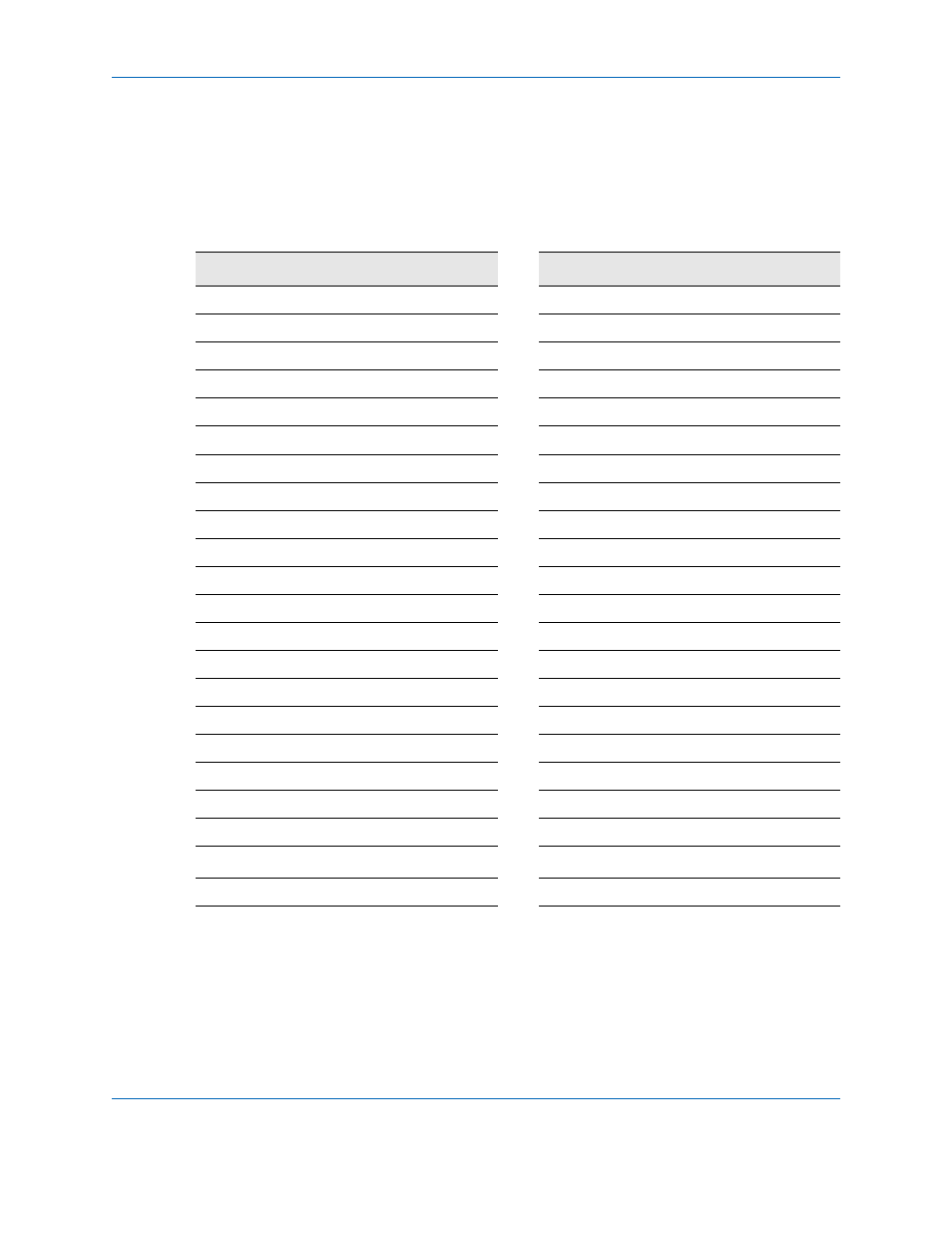
The following table describes the SiliconDrive 1.8" Drive 44-pin IDE connector
signals.
Table 7: Pin Assignments
Pin
IDE-ATA
Pin
IDE-ATA
1
-RESET
2
GND
3
D7
4
D8
5
D6
6
D9
7
D5
8
D10
9
D4
10
D11
11
D3
12
D12
13
D2
14
D13
15
D1
16
D14
17
D0
18
D15
19
GND
20
KEY
21
DMARQ
22
GND
23
-IOWR
24
GND
25
-IORD
26
GND
27
IORDY
28
-CSEL
29
-DMACK
30
GND
31
INTRQ
32
-IOCS16
33
A1
34
-PDIAG
35
A0
36
A2
37
-CS0
38
-CS1
39
-DASP
40
GND
41
V
CC
42
V
CC
43
GND
44
NC