Chapter 6. down load function, General, Sio interface specification – Sharp ER-A440 User Manual
Page 30: Location of connector pins
CHAPTER 6. DOWN LOAD
FUNCTION
1. General
RAM data can be transmitted in the following two methods.
Save the data before servicing as follows:
ECR
←→
ECR
•
Cable: 9 pin D-SUB – 9 pin D-SUB
Fig. 1-1
ECR
←→
ER-02FD
•
Cable: 9 pin D-SUB – 25 pin D-SUB
Fig. 1-2
2. SIO interface specification
1) Operation:
Simplex
2) Line configuration:
Direct connect
3)
Data
rate:
19200, 9600, 4800, 2400, 1200, 600,
300BPS (Selected by SRV JOB#903-A)
4) Sync mode:
Asynchronous
5) Checking:
Vertical parity (odd)
6) Code:
7 bits (ASCII)
7) Bit sequence:
LSB first
8) Line level:
RS232 level
9) Data forma:
FIg. 2-1
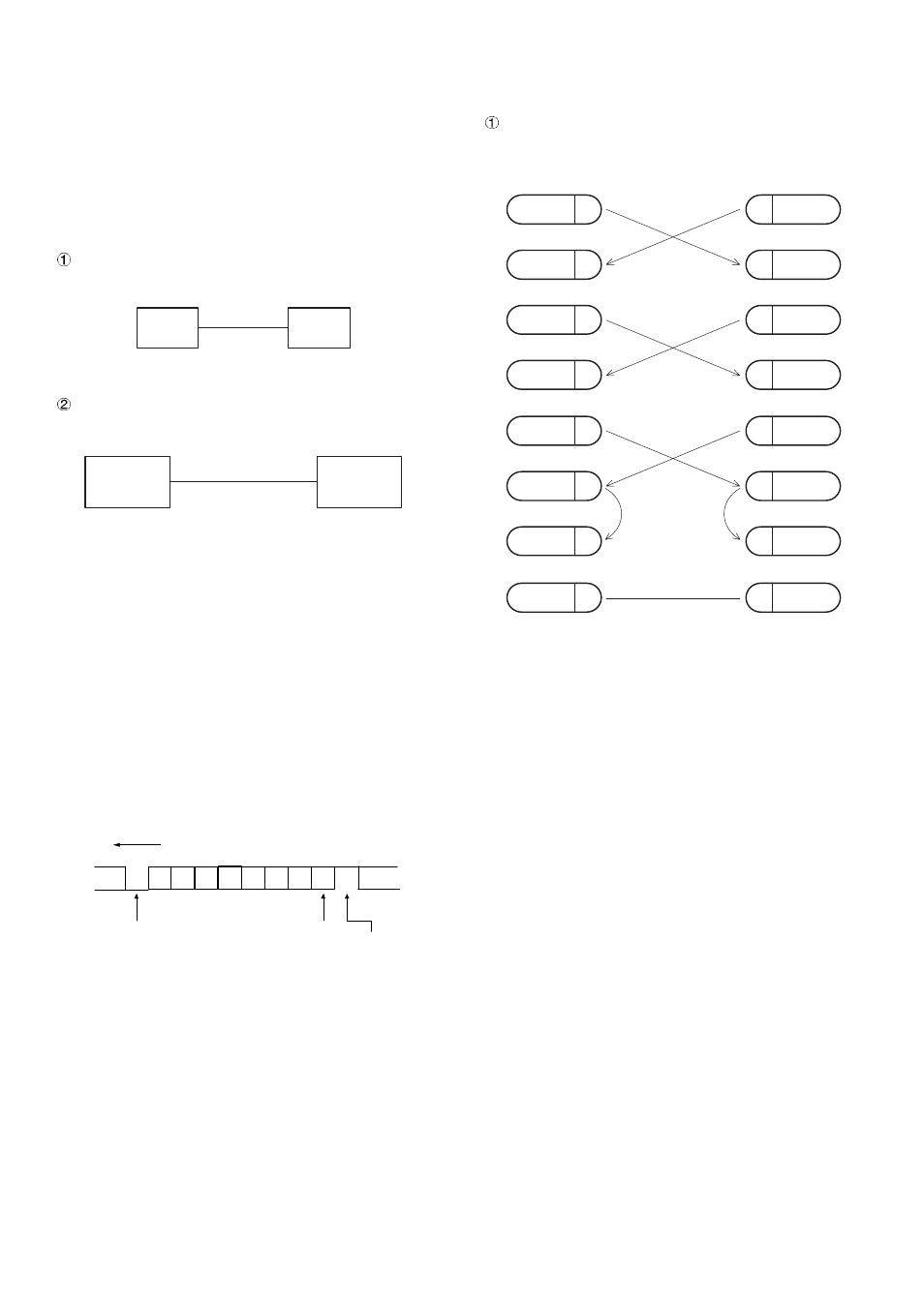
3. Location of connector pins
ECR-ECR cable
Fig. 3-1
ECR
ECR
ECR
ER-02FD
P
b1
b2
b3
b4
b5
b6
b7
LSB
MSB
Start bit
Parity
bit
Stop
bit
SD
3
SD
RD
CTS
RD
2
6
8
3
2
6
8
5
5
SG
RTS
7
DCD
1
DTR
4
DSR
7
1
4
ECR
CTS
SG
RTS
DCD
DTR
DSR
9PIN D-SUB
9PIN D-SUB
SD : TRANSMITTED DATA
RD : RECEIVED DATA
DTR: DATA TERMINAL READY
DSR: DATA SET READY
RTS: REQUEST TO SEND
DCD: DATA CARRIER DETECTOR
CTS: CLEAR TO SEND
ECR
6 – 1