4) printer sensor circuit, 5) dot solenoid drive circuit, 6) paper feed circuit – Sharp ER-A440 User Manual
Page 21
When an abnormal load is applied to the mechanism, the DP (Dot
Pulse) frequency is checked to prevent against the motor burn-out,
the timing belt shift, and gear damage. If the following condition is
made, the CPU stops the motor rotation.
When starting the motor: When the cycle from starting to the
100th pulse of DP is 16ms. (The one pulse cycle of DP is normally
555us.)
During constant rotation of the motor: When one pulse of DP is
1100us or more.
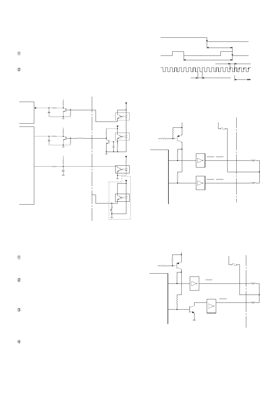
4) Printer sensor circuit
The printer supplies the RP (Reset Pulse) signal, the HP (Home
Position) signal, and the DP (Dot Pulse) signal) to control printing
timing and conduction timing of solenoids. It also supplies the VPJ
signal to detect the presence of validation paper. These sensor are
photo interrupters.
RP (RJRST) signal
This signal is outputted once for every reciprocating motion of the
print head. It indicates the reference position of the HP signal.
The rear edge of RP (OFF -- ON) is used as the signal.
HP signal
The pulse signal is outputted from the slit in the disk installed to
the DC motor shaft. It is used as the reference signal for starting
counting of the DP signal. It is generated once for twenty DP
signals. The rear edge of the HP signal (ON -- OFF) immediately
after generation of the RP signal is used as the signal.
DP (RJTMG) signal
The pulse signal is outputted from the slit in the disk installed to
the DC motor shaft. It is used as the control signal for the print
solenoid and the paper feed solenoid.
The front edge of the output signal (ON -- OFF) is used as the
signal.
VPJS (VPJ) signal
The presence of a validation card is detected by interruption of the
photo interrupter LED light by the validation card.
5) Dot solenoid drive circuit
The DOT1
∼
DOT7 (the dot solenoid drive signals from the MPCA7)
are pulled up by the VRESE and converted into LOW by the driver IC.
A +24V voltage is applied to the solenoid. This operates the dot wire.
6) Paper feed circuit
The PFJ0 (the journal paper fed signal from the MPCA7) and the
PFR0 (the receipt paper feed signal) are pulled up by the VRESE and
converted into LOW level. A +24V voltage is applied to the solenoid.
This operates the paper feed solenoid.
R207
Q6
C93
+5V
R206
R126
HP
HP
+5V
R132
Q8
C91
+5V
R131
R130
RJTMG
DP
+5V
C228
+5V
RJRST
RP
+5V
VPS
VPJS(NU)
+5V
R129
R133
MPCA7
CPU
R1134
NOT USED
OFF
ON
555µs(TYP.)(516~590µS)
#1 #2 #3 #4
+5V
GND
+5V
GND
ON
ON
+5V
GND
OFF
OFF
RP
HP
DP
Relation ship among RP/HP/DP
1.5ms or above
The first HP after turning
OFF/ON RP.
20 cycles of DP (TYP.11.1ms)
50µs above
50µs above
Print area
* The waveforms are those indicated with arrow in Fig.3-3.
VRESC
R146
R145
Q9
R149
DOT1
~DOT4
IC15
DOT1~DOT4
IC16
DOT5~DOT7
DOT5
~DOT7
MPCA7
+5V
+24V
R152
R153
R155
VRESC
R146
R145
Q9
PFJ0
PFJ0
PFR0
MPCA7
+5V
+24V
PFR0
Q11
F2
IC16
IC18
R156
R161
4 – 14