Part no. and description qty, Hardware identification chart – Stamina Products 55-2065 User Manual
Page 5
Length
5
Part No. and Description
Qty
mm.
in.
INCHES
MILLIMETERS
1
1/2
0
2
1/2
3
1/2
4
1/2
5
1/2
6
1/2
0
10
20
30
40
50
60
70
80
90
100
110 120
130
140 150
6
8
10
12
3/16"
5/16"
1/2"
3/8"
1/4"
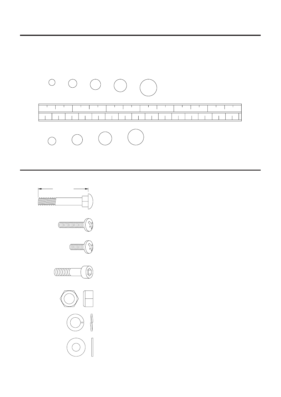
HARDWARE IDENTIFICATION CHART
Place washers, the end of bolts or screws on the
circles to check for the correct size. Use the small
scale to check the sizes of bolts and screws.
This chart is provided to help identify the hardware used in the assembly process. After unpacking the unit,
open the hardware bag and make sure that you have the following items:
NOTE: Some of the hardware items listed may be attached to other parts.
88
Lock Washer (M8)
8
65
Bolt, Round Head (M6 x 1 x 25mm)
4
66
Bolt, Round Head (M6 x 1 x 35mm)
4
63
Carriage Bolt (M8 x 1.25 x 85mm)
2
78
Screw, Round Head (M5 x 12mm)
2
83
Nylock Nut (M6 x 1)
4
85
Nylock Nut (M8 x 1.25 x 8mm thick)
8
86
Nylock Nut (M10 x 1.25)
2
89
Washer (M8)
2
90
Washer (M10)
2
68
Bolt, Socket Head (M8 x 1.25 x 35mm)
2
70
Bolt, Socket Head (M8 x 1.25 x 25mm)
4
71
Bolt, Socket Head (M8 x 1.25 x 50mm)
2
72
Bolt, Socket Head (M8 x 1.25 x 90mm)
2