X3. how to install the indoor unit – Sanyo AHX0952 User Manual
Page 25
25
X
3. HOW TO INSTALL THE INDOOR UNIT
■ 4-Way Air Discharge Semi-Concealed Type (X Type)
3-1. Preparation for Suspending
This unit uses a drain pump. Use a carpenter’s level to check that the
unit is level.
3-2. Suspending the Indoor Unit
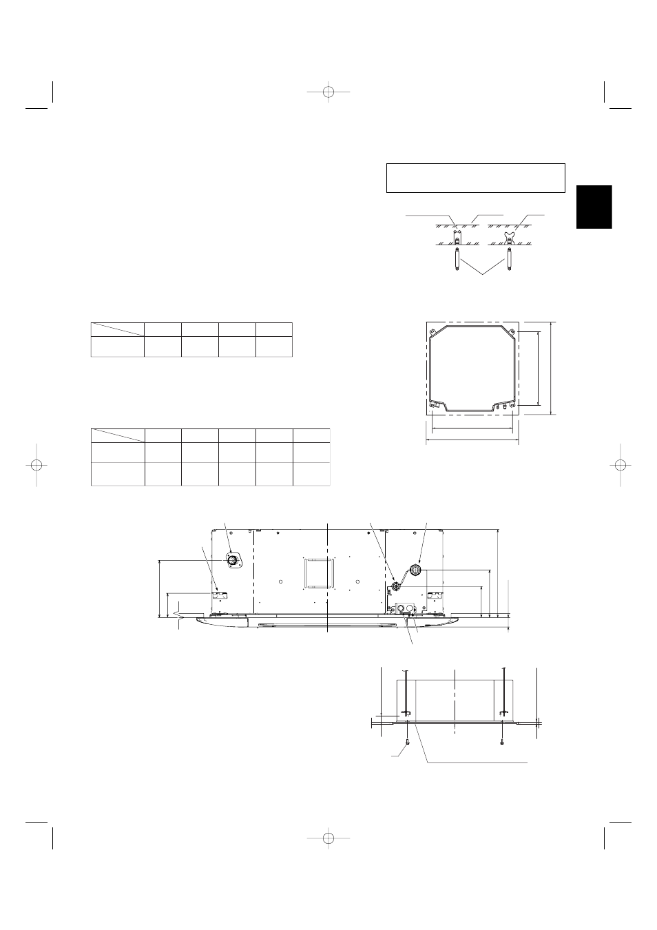
(1) Fix the suspension bolts securely in the ceiling using the method
shown in the diagrams (Figs. 3-1 and 3-2), by attaching them to the
ceiling support structure, or by any other method that ensures that
the unit will be securely and safely suspended.
(2) Follow Fig. 3-2 and Table 3-1 to make the holes in the ceiling.
Table 3-1
Unit: in. (mm)
(3) Determine the pitch of the suspension bolts using the supplied full-
scale installation diagram. The diagram and table (Fig. 3-3 and
Table 3-2) show the relationship between the positions of the sus-
pension fitting, unit, and panel.
Table 3-2
Fig. 3-1
Fig. 3-2
Hole-in-anchor
Hole-in-plug
Concrete
Insert
Suspension bolt (M10 or 3/8")
(field supply)
Type
A
B
C
D
31-1/32
(788)
28-15/32
(723)
34-27/32
(885)
34-27/32
(885)
12, 18, 24, 36
Length
Type
A
B
C
D
4-29/64
(113)
6-13/16
(173)
8-17/64
(210)
10-5/64
(256)
12, 18, 24
4-29/64
(113)
6-13/16
(173)
8-17/64
(210)
E
3-15/32
(88)
3-15/32
(88)
12-9/16
(319)
36
Length
D (ceili
ng
ope
n
ing
dime
ns
io
n
)
C (ceiling opening dimension)
A (suspension bolt pitch)
B (
sus
pe
ns
io
n
bolt pitch)
Drain outlet(other side)
(VP25)
Suspension lug
Refregerant tubing joint(liquid side)
Refregerant tubing joint(gas side)
Power supply outlet
Inter-unit control wiring
D
E
A
B
C
1-
3
/8
(
3
5)
Note: For DC Fan Tap Change Procedure
for 4-Way Cassette, see page 31.
Fig. 3-4
Full-scale installation diagram
(printed on top of container box)
Supplied bolt
Ov
er 19/
3
2 (15)
15/
3
2 – 4
3
/64
(12 – 17)
3-3. Placing the Unit Inside the Ceiling
(1) When placing the unit inside the ceiling, determine
the pitch of the suspension bolts using the supplied
full-scale installation diagram. (Fig. 3-4)
Tubing and wiring must be laid inside the ceiling
when suspending the unit. If the ceiling is already
constructed, lay the tubing and wiring into position
for connection to the unit before placing the unit
inside the ceiling.
Unit: in. (mm)
Unit: in. (mm)
Unit: in. (mm)
Fig. 3-3
07-056 Mini_ECOi_II_NA 3/19/07 2:40 PM Page 25