Sanyo AHX0952 User Manual
Page 10
10
Table 1-10 Indoor Unit Tubing Connection (
1
,
2
...
n–1
)
ш5/8" (ш15.88)
ш1/2" (ш12.7)
ш1/4" (ш6.35)
ш3/8" (ш9.52)
7
9
12
18
36
24
48
Indoor unit type
Gas tubing
Liquid tubing
Unit: in. (mm)
24,200 (2.5 hp)
ш5/8" (ш15.88)
ш1/2" (ш12.7)
ш3/4" (ш19.05)
ш3/8" (ш9.52)
ш3/8" (ш9.52)
24,200 (2.5 hp)
–
38,200 (4 hp)
47,800 (5 hp)
52,900 (6 hp)
Below BTU/h
Over BTU/h
Tubing size
Total capacity
after distribution
Gas tubing
Liquid tubing
hp = horsepower
Unit: in. (mm)
1-5. Tubing Size
Table 1-8 Main Tubing Size (LA)
ш3/4" (ш19.05)
6
Unit: in. (mm)
52,900 (15.5)
ш3/8" (ш9.52)
ш5/8" (ш15.88)
4
38,200 (11.2)
BTU/h (kW)
System horsepower
Gas tubing
Liquid tubing
Table 1-9 Main Tubing Size After Distribution (LB, LC...)
Note: In case the total capacity of connected indoor units exceeds the total capacity of the outdoor units, select the main
tubing size for the total capacity of the outdoor units.
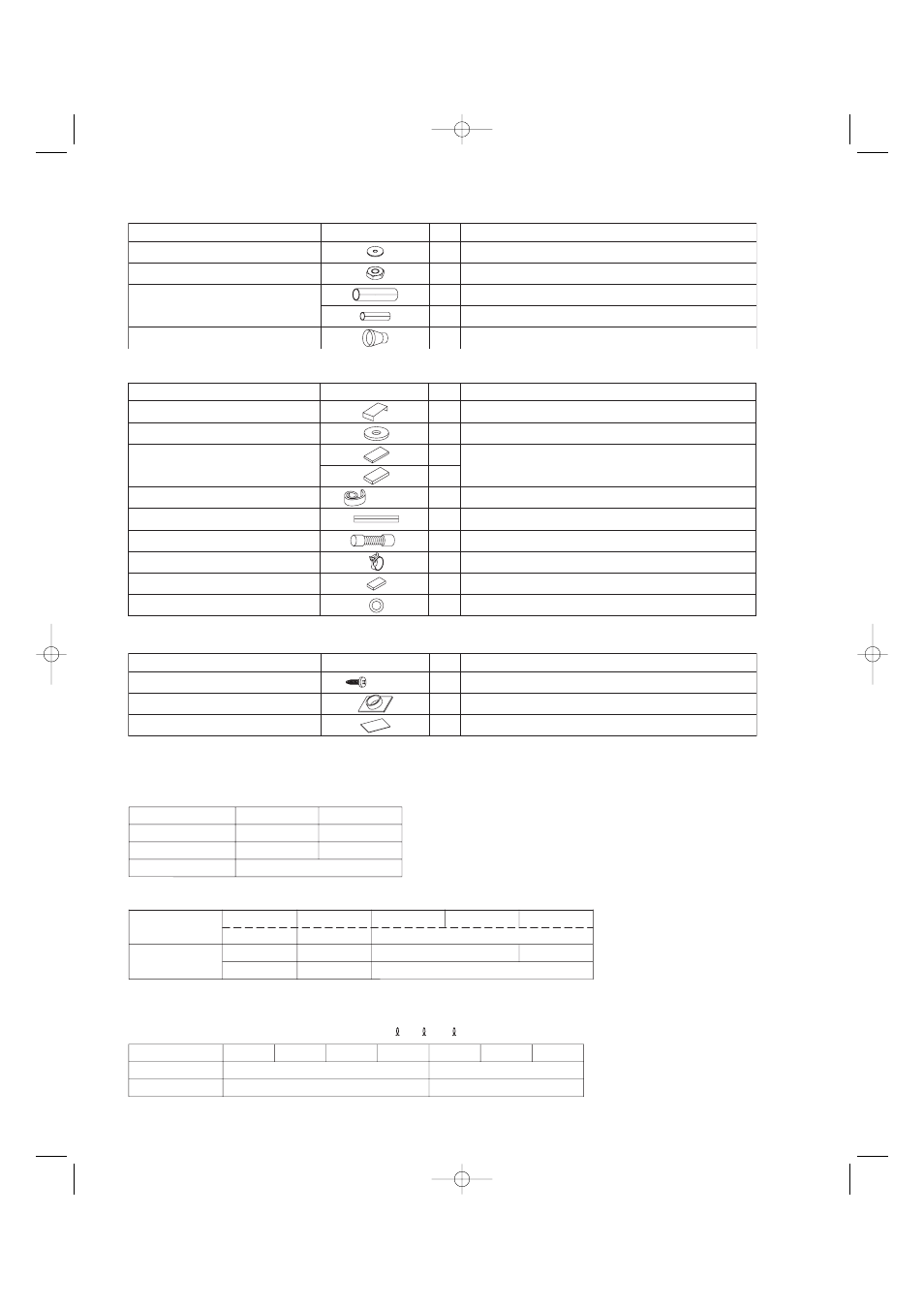
Table 1-5 (Concealed Duct High-Static Pressure)
Table 1-6 (Ceiling-Mounted)
Part Name
Figure
Q’ty
Remarks
8
For suspending indoor unit from ceiling
Washer
8
For suspending indoor unit from ceiling
Nut
1
For gas tube
Flare insulator
1
For liquid tube
1
For drain pipe connection
Drain socket
Part Name
Figure
Q’ty
Remarks
Full-scale installation diagram
1
Printed on container box
Washer
4
For temporarily suspending indoor unit from ceiling
Flare insulator
2
For gas and liquid tube joints
2
Insulating tape
2
For gas and liquid tubes flare nuts
Vinyl clamp
8
For flare and drain insulators
Drain insulator
1
For drain hose joint
Gum eyelet
1
For power supply inlet
Drain hose
1
For main unit and PVC pipe joints
Hose band
2
For drain hose connection
L5-1/2"
T3/16"
T1/8"
White
(heat-resisting)
Table 1-7 (Wall-Mounted)
5/32"
× 1"
Part Name
Figure
Q’ty
Remarks
10
For fixing the rear panel
Tapping screw
1
For improved tubing appearance
Plastic cover
1
For insulating flare nut (2452 type only)
Insulator
07-056 Mini_ECOi_II_NA 3/19/07 2:40 PM Page 10