Schneider Electric POWERLOGIC PWRSRV750 User Manual
Page 6
Chapter 1—Introduction
63230-216-207/A3
Overview
9/2002
© 2002 Schneider Electric All Rights Reserved
2
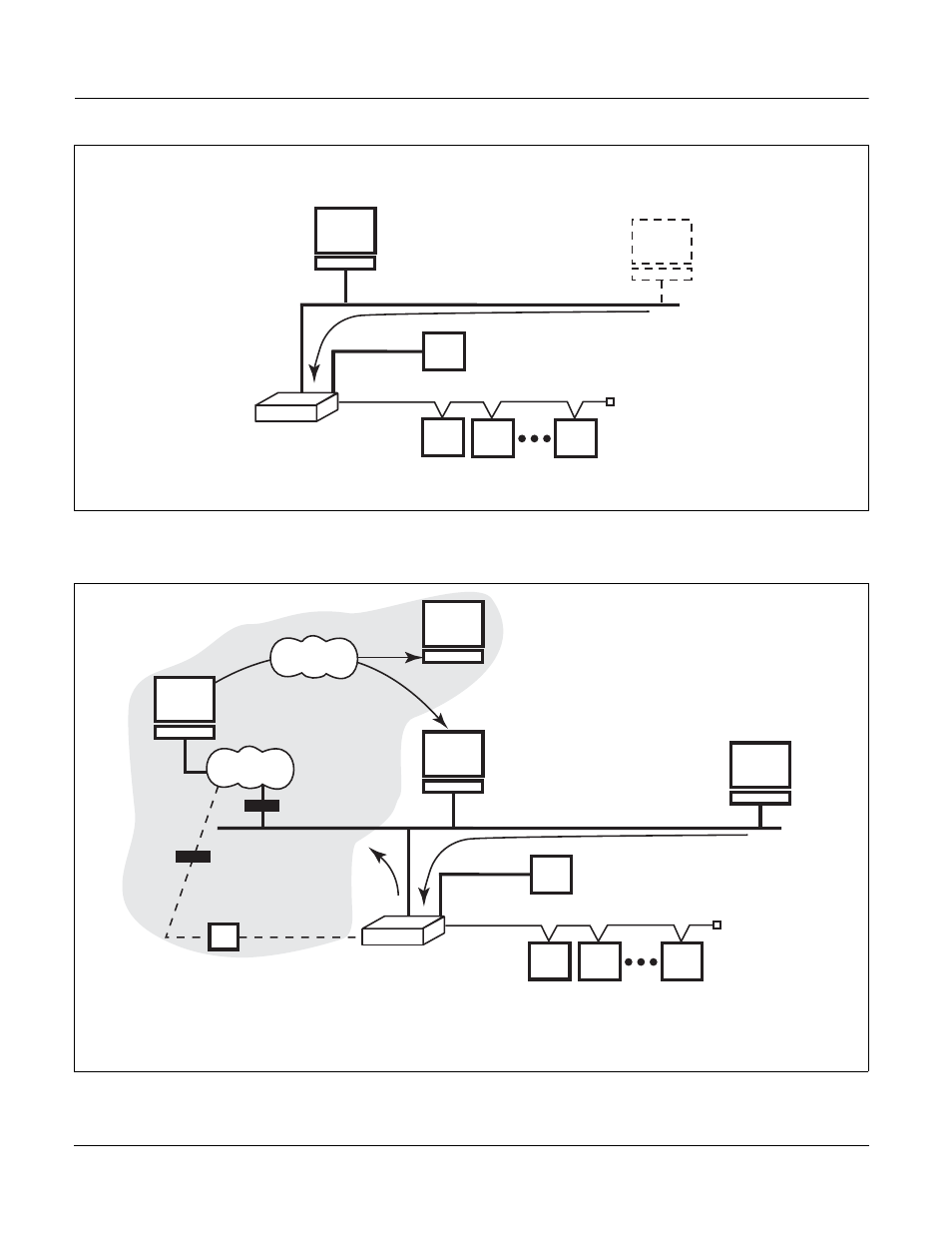
Figure 1–2: The Power Server used as a standalone system monitoring device
Figure 1–3: The Power Server used as a gateway device with SMS and a web server
Initial setup
via
NetMeeting
Power Server used as a
component of the
POWERLOGIC System
Mixed-mode daisy chain
Device setup for the
POWERLOGIC System
Web browser
Optional
touch screen
30
70305
9
PC with
System Manager
Software (SMS)
Power Server used as
a gateway
Mixed-mode daisy chain
PUSH application
sending data to
enterprise
via Ethernet
via
Modem
Internet
Internet
POWERLOGIC Enterprise System
307
03054
POWERLOGIC
Enterprise System
View reports via
Internet browser
Firewall
Firewall
NOTE: The shaded area depicts a POWERLOGIC Enterprise System. Contact
POWERLOGIC Engineering Services for information on this type of application.
Optional
touch screen
Web browser