Chapter 4— connections, Connections summary, Chapter 4—connections – Schneider Electric POWERLOGIC PWRSRV750 User Manual
Page 13
63230-216-207/A3
Chapter 4—Connections
9/2002
Connections Summary
9
© 2002 Schneider Electric All Rights Reserved
CHAPTER 4—CONNECTIONS
CONNECTIONS SUMMARY
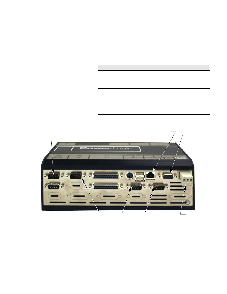
The Power Server connections are described in this chapter. Table 4–1
briefly describes each connection.
Figure 4–1: Power Server connections
Table 4–1:
Connections description
Connection
Description
UTP Port
Ethernet connection. Standard RJ-45 port for connection of
unshielded twisted-pair (10/100 BaseT) Ethernet cable. Category
5 recommended.
Control Power
Three-pin connector for 24 Vdc connection.
COM 1 RS-232
RS-232 serial port for configuring network settings using a PC.
COM 2 RS-232
Touchscreen serial cable port.
COM 3 RS-485
RS-485 comm ports for connecting POWERLOGIC or Modbus/
JBUS devices to the Power Server.
COM 4 RS-485
VGA output
Connect to touchscreen.
COM 1
RS-232 serial port
Setup connection
COM 2
RS-232 Touchscreen serial
connection
UTP Port
Control Power
RS-232
RS-232
RS-485
RS-485
COM 3
RS-485 port
COM 4
RS-485 port
3070
3006
VGA output to
Touchscreen
monitor