Asus P4B-E User Manual
Page 58
2-36
Chapter 2: Hardware information
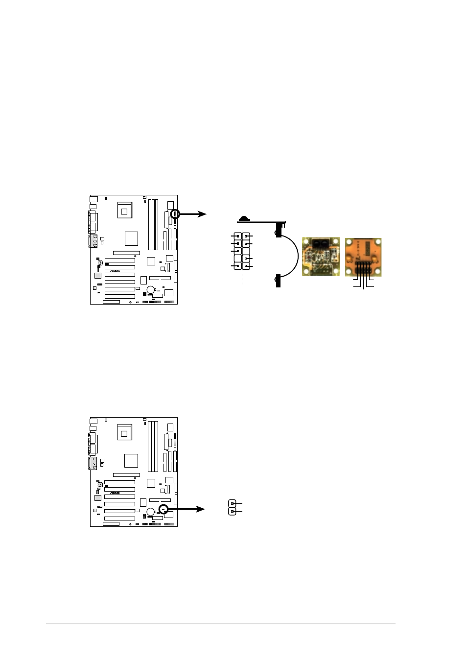
18. Power supply thermal connector (2-pin TRPWR)
If your power supply has a thermal monitoring feature, connect its
thermal sensor cable to this connector.
Figure 2-52
Power Supply Thermal Connector
®
P4B-E
P4B-E Power Supply Thermal Connector
TRPWR
Ground
TRPWR
®
P4B-E
P4B-E Infrared Module Connector
Standard Infrared (SIR)
Front View
Back View
+5V
IRTX
IRRX
(NC)
GND
SIR
KBPWR
IRRX
IRTX
GND
CIRTX
GND
CIRRX
KBPWR
CIR
1
17. Infrared module connector (5-1 pin IR_CON)
This connector supports an optional wireless transmitting and receiving
infrared module. This module mounts to a small opening on system
chassis that support this feature. Use the five pins as shown in Back
View and connect a ribbon cable from the module to the motherboard
SIR connector according to the pin definitions.
If you installed an infrared module, enable the UART2 Use Standard
Infrared parameter in BIOS to set UART2 for use with IR. See section
“4.4.2 I/O Device Configuration” for details.
Figure 2-51
Infrared Module Connector
- P5B Premium Vista Edition (188 pages)
- P5B (140 pages)
- P5B (56 pages)
- P5KPL-VM/1394/SI (94 pages)
- M2N68-CM (28 pages)
- P5AD2-E Premium (2 pages)
- P5GD1-VM (88 pages)
- P5AD2 Premium (8 pages)
- P5GD1-VM (92 pages)
- DELUXE A7N8X-E (114 pages)
- P5KPL-AM SE (40 pages)
- P5KPL-AM SE (38 pages)
- P5KPL-AM SE (62 pages)
- P4S8X-X (64 pages)
- P5K-VM (98 pages)
- K8V-X SE (82 pages)
- M2N68-AM SE2 (40 pages)
- P4P800 SE (125 pages)
- P4P800 SE (16 pages)
- DELUXE SERIES M3A32-MVP (176 pages)
- P5AD2 Deluxe (148 pages)
- M4A79 Deluxe (122 pages)
- A7V266-E (108 pages)
- Application Manual (8 pages)
- Application Manual (2 pages)
- Application Manual (6 pages)
- Application Manual (9 pages)
- Application Manual (3 pages)
- Application Manual (1 page)
- Application Manual (5 pages)
- Application Manual (11 pages)
- Application Manual (10 pages)
- Application Manual (4 pages)
- M4A88T-I DELUXE (70 pages)
- M4A88T-I DELUXE (44 pages)
- P9X79 DELUXE (2 pages)
- RAMPAGE IV GENE (1 page)
- P9X79 (156 pages)
- P8H61-M PLUS V3 (64 pages)
- A85XM-A (78 pages)
- M4A78L-M LE (64 pages)
- M2N68-AM (62 pages)
- M2N68-AM (38 pages)
- M2N68-AM (96 pages)
- Blitz Formula (1 page)